
Machinery, Engines, and Equipment on the RMS Titanic: A Look at the Ship’s Cutting-Edge Technology
Machinery, Engines, and Equipment utlized by the Titanic include Refrigerating Machines, Watertight Doors, Generating Plant, Dynamos, Equalizing Switchgear, Engine Room Switchboard, Cargo Winch, Master Clock, and many more.
Machinery, Engines, and Equipment on the RMS Titanic
Overview and Relevance to Ocean Travel 🌍🚢
The RMS Titanic, renowned for its engineering marvels, featured cutting-edge machinery, engines, and equipment designed to make it the most advanced and luxurious ship of its time. The machinery and technology that powered the Titanic, such as the refrigerating systems, watertight doors, and generating plants, were a testament to the peak of industrial progress in the early 20th century. Examining these systems offers invaluable insights into the sophistication of the Titanic’s design and the impact of its technological advancements on ocean travel at the time.
For teachers, students, genealogists, and historians, this collection of images and detailed descriptions highlights the complex and innovative engineering that powered the Titanic. These visuals serve as key resources for exploring the technological landscape of the early 1900s, the role of engineering in maritime safety, and the interplay of luxury and technology aboard one of the most famous ships in history.
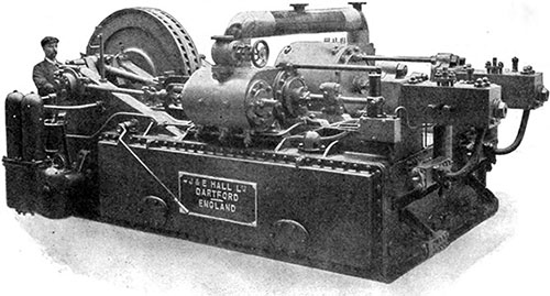
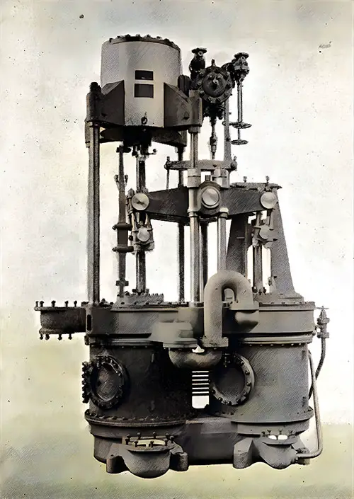
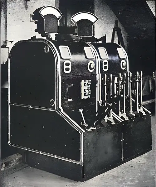
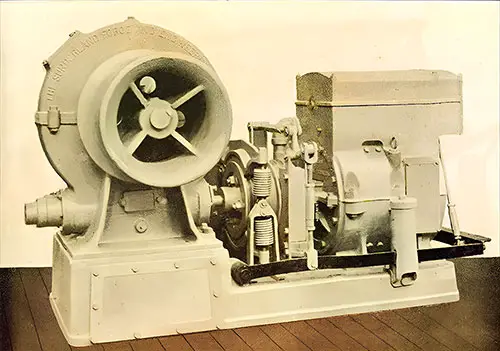
One of the Refrigerating Machines on the 'Titanic,' Built by J & E Hall Ltd. in Dartford, England. Ice and Cold Storage (July 1911) p. 159. | GGA Image ID # 104b2e00b9
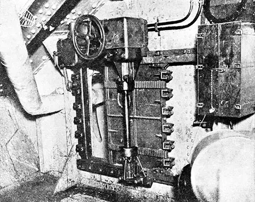
One of the Electrically Operated, Double-Cylinder, Watertight Doors in the Forward Bulkheads of the "Titanic," Which Were Closed from the Bridge. Popular Mechanics Magazine (June 1912) p. 798. | GGA Image ID # 1080a486c9
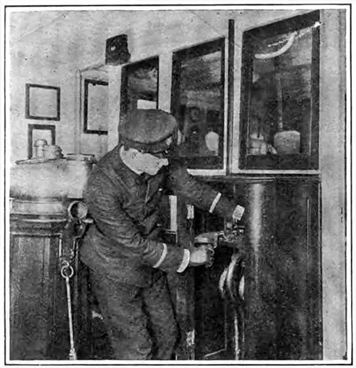
Closing All Hydraulically Operated Doors from the Bridge. Scientific American (27 April 1912) p. 380a. | GGA Image ID # 10a3aee16b
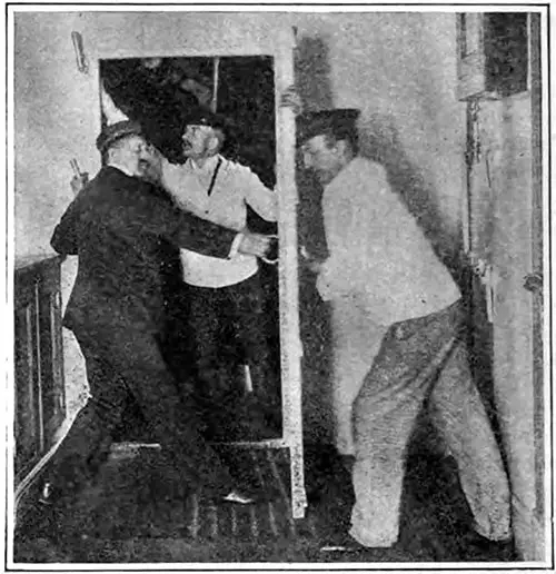
Closing Water-Tight Door, Above the Water Line, by Hand Power. Scientific American (27 April 1912) p. 380b. | GGA Image ID # 10a407741a
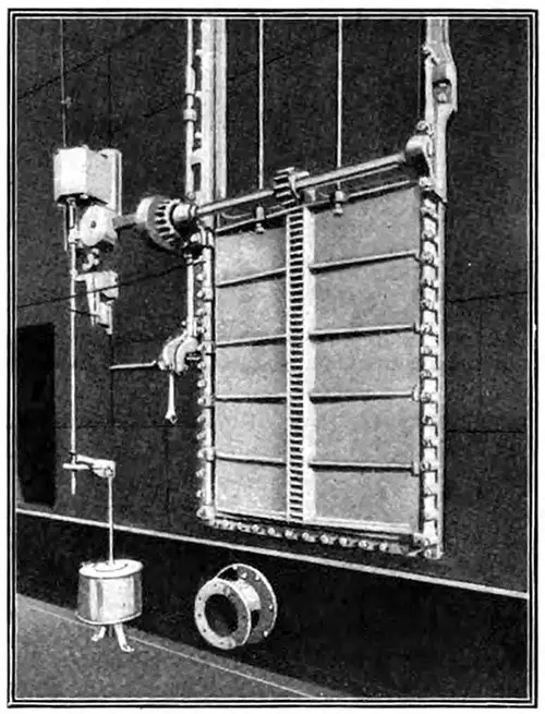
Electrically Operated Bulkhead of the General Type Installed on the Titanic. Scientific American (27 April 1912) p. 380c. | GGA Image ID # 10a419ff45
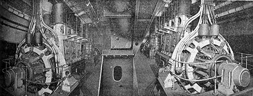
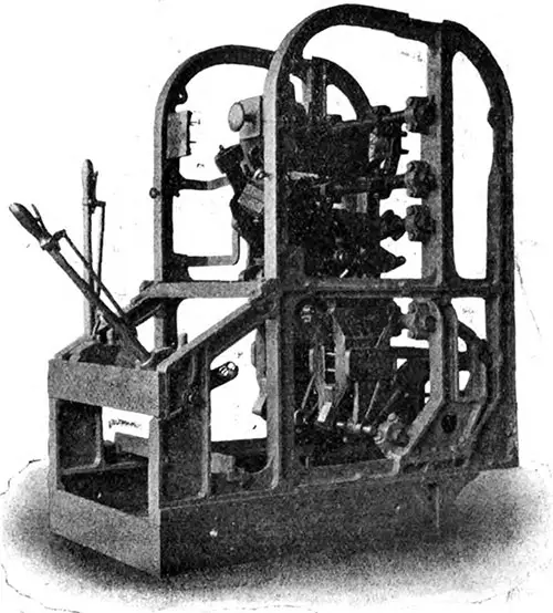
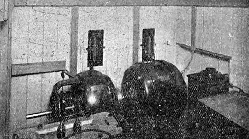
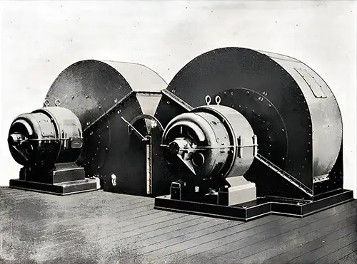
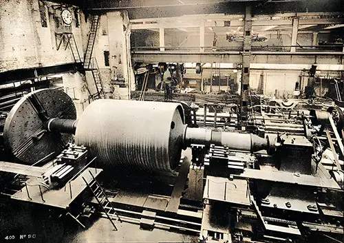
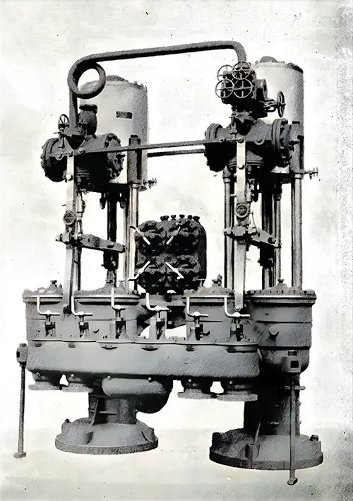
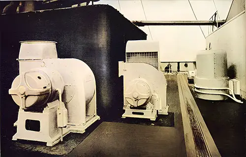
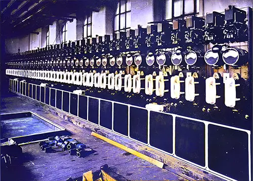
General View of Generating Plant. The main generating plant, which is probably the largest electrical equipment that has been installed up to the present for marine work, consists of four 400 kw. Engines and dynamos, manufactured by Messrs. W. H. Allen, Son & Co., of Bedford, and having a collective output of 16,000 amps. at 100 volts, thus exceeding in current capacity many electrical central stations. The Electrician (28 July 1911) p. 615. | GGA Image ID # 10f08c01b9
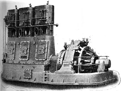
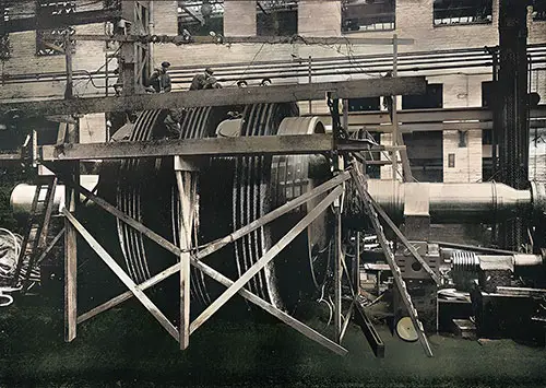
One of the Main Generating Sets on the Olympic. The Electrician (28 July 1911) p. 617. | GGA Image ID # 10f0a9c5e1
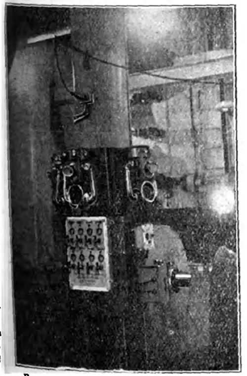
Main Switchgear of Dynamo Nos. 1 and 2. Each set of main switchgear is operated by a row of five interlocked handle levers. The two outer handles are connected mechanically with the lighting and power equaling switches, respectively, and are interlocked so that they must be closed before the next handles, which operate the lighting and power main bus-bar selector switches, can be worked. The central handle is for closing and gripping the circuit breaker, and is also interlocked with the selector switch handles, so that the circuit breaker can only be closed and gripped when the selector switches are both in the "off" position. The Electrician (28 July 1911) p. 617. | GGA Image ID # 10f0bde871
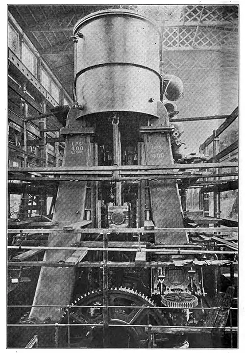
View of a Main Generator Control Pillar During Construction, Showing the Circuit Breaker Above and the Two Selector Switches Below. The Electrician (28 July 1911) p. 618. | GGA Image ID # 10f139dfdc
Equalizing Switchgear. The enclosing case is arranged to open in two parts, the left-hand half being here shown open. The connecting links of some of the switches are shown on the right-hand side. The Electrician (28 July 1911) p. 618. | GGA Image ID # 10f1962a40
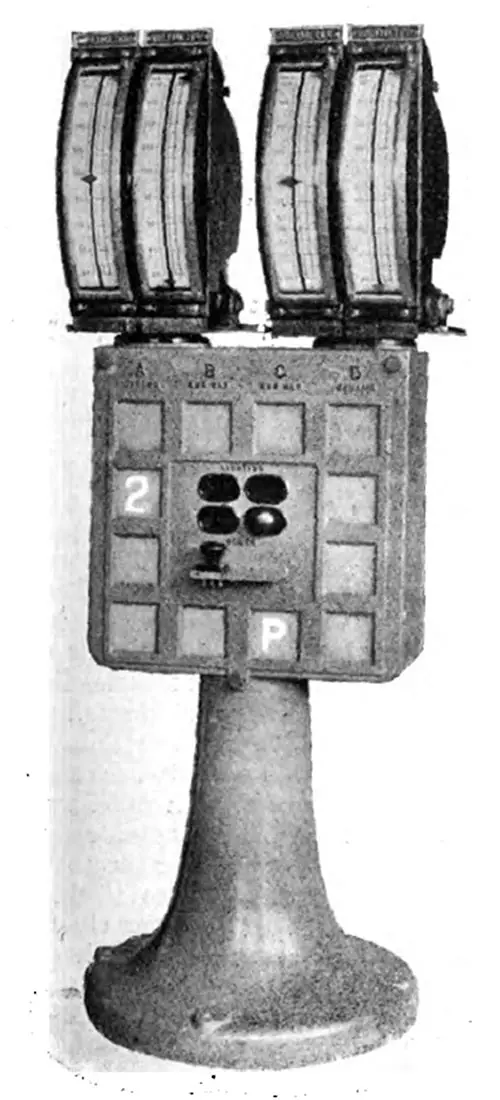
Main Voltmeter Pillar. Voltmeters are used also for paralleling, are carried on a cast-iron pillar amidships between the main dynamo control gear. The voltmeters themselves are mounted in pairs; each pair being arranged so that they can swing round through 220 deg. The Electrician (28 July 1911) p. 619. | GGA Image ID # 10f1978a72
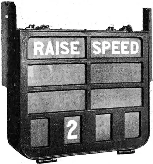
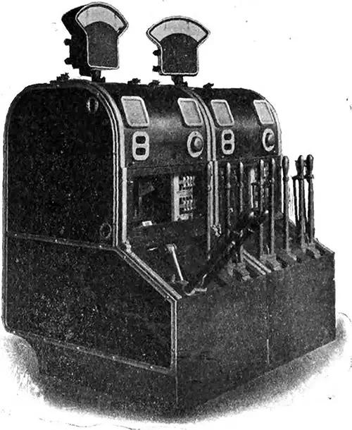
Engine Room Signal from Switchboard. The signs, reading “start,” “raise speed,” “lower speed” and “stop,” combined with the number of the machine to which the signal applies, are visible in white letters on a red background when the lamps are illuminated by pressing a signal knob. The Electrician (28 July 1911) p. 619. | GGA Image ID # 10f1d4d5b4

Stoking Indicator; Helm Indicator; and Boiler Room Orders Telegraph. The Electrician (4 August 1911) p. 658. | GGA Image ID # 1f8d088856

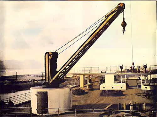
2 1/2 Ton Electric Crane. One of the little discomforts sometimes associated with modern ocean travelling is the noise caused by winches and other deck appliances, and although when on the high seas these are not much in evidence, yet when approaching port it is sometimes necessary to use them, as for instance when handling mails or passengers' luggage preparatory to dis embarkation. With a view to avoiding this on the “Olympic," the aid of electricity has again been invoked, with the result that all the winches in the vicinity of the passenger accommodation and the cargo cranes are electrically driven. The latter are made by Messrs. Stothert & Pitt, six having of 50 cwt. each, and two of 30 cwt. each. These cranes are fitted at the three after hatches and at the forward hatch near the passenger quarters. The Electrician (4 August 1911) p. 659. | GGA Image ID # 1f8dba40e2

3-Ton Electric Cargo Winch. In addition to the electric cranes, there are four 3-ton electric cargo winches at the hatches, as well as four 15-cwt. electric boat winches made by the Sunderland Forge and Engineering Co. Ltd. The Electrician (4 August 1911) p. 659. | GGA Image ID # 1f8dcf0600
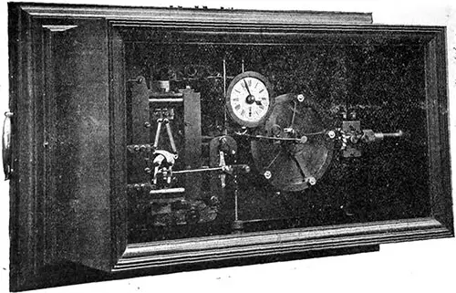
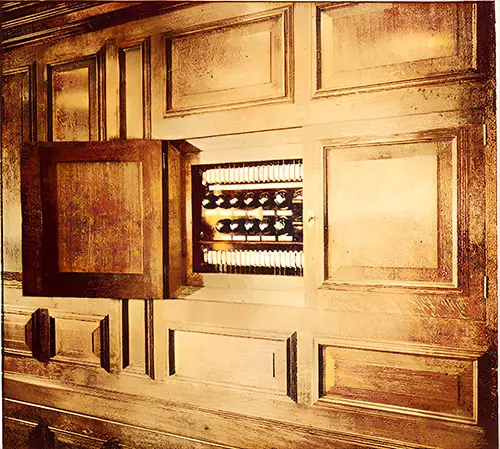
Magneta Master Clock. The clocks, of which there are 48 throughout the vessel, are all actuated electrically, and worked in complete synchronism, so that each register exactly the same time; they are controlled by a master clock (Fig. 14) placed in the chart room under the control of the officers, who can set them backwards and forwards according to the longitude. The Electrician (4 August 1911) p. 660. | GGA Image ID # 10f1e1da34
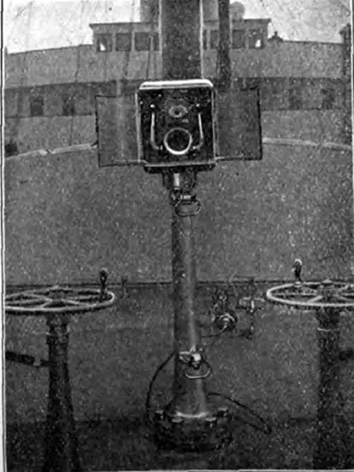
Forecastle Telephone. The Electrician (4 August 1911) p. 660. | GGA Image ID # 10f22d5c98
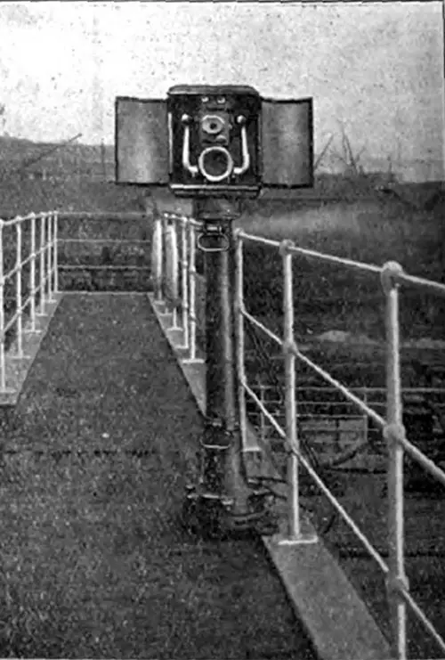
Poop Telephone Instrument. The Electrician (4 August 1911) p. 660. | GGA Image ID # 10f22f4ecd
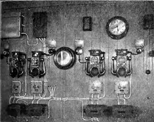
Wheelhouse Telephones. In the wheelhouse on the bridge (Fig. 17) four instruments are fitted, and each telephone is provided with an indicating device, and in addition to a flag showing, as is usual, a signal lamp is caused to glow upon a call being received. The Electrician (4 August 1911) p. 661. | GGA Image ID # 10f25609d1
Engine Room Telephones. In the engine room (Fig. 18) three telephones are employed, and the instrument for communicating with the boiler rooms operate in conjunction with a combined switch and indicator lighting both lamp and flag signals as previously referred to. In each boiler room, the telephone is mounted within a metal hood, and in addition a special calling receiver is provided at each station as well as a visual indicator. The Electrician (4 August 1911) p. 661. | GGA Image ID # 10f270ccc8
Part of Marconi Transmitting Apparatus in Silence Cabin. The Electrician (4 August 1911) p. 661. | GGA Image ID # 10f2a38382
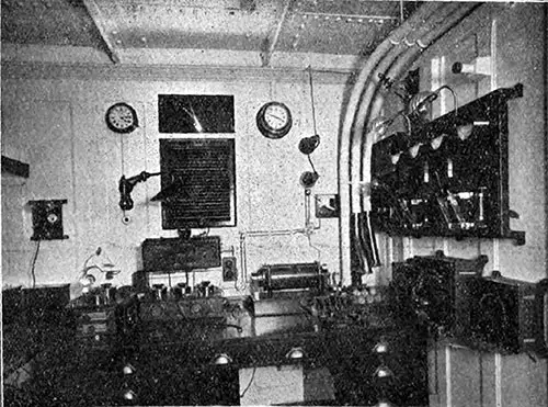
Marconi Apparatus in Operating Cabin. No modern liner is complete without a wireless telegraph installation. With such an equipment not only is communication with ship or shore possible in case of accidents, but the passenger is enabled during the voyage to keep himself in touch with the world's news. The “wireless " apparatus on the “Olympic '' is of the Marconi type and consists of a 5 kw. motor-generator set combined with the latest type of valve receiver installed as a standby. The installation is designed to provide, when employed with a suitable aerial having a mean height of 170 ft., a working range of 250 nautical miles over water, and a maximum range considerably exceeding the above figure. The Electrician (4 August 1911) p. 661. | GGA Image ID # 10f2cc2d4c
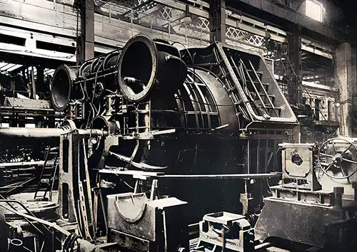
View of the Starboard Reciprocating Engines on the RMS Titanic. It may be stated that both triple screw steamers Titanic and Olympic have propelling plants consisting of reciprocating engines and a low-pressure steam turbine. The two sets of reciprocating engines, one driving each wing shaft are of the four crank triple type and are arranged to work at 215 pounds per square inch and to exhaust at 9 pounds absolute. The International Steam Engineer (November 1911) p. 744. | GGA Image ID # 1055751ec4
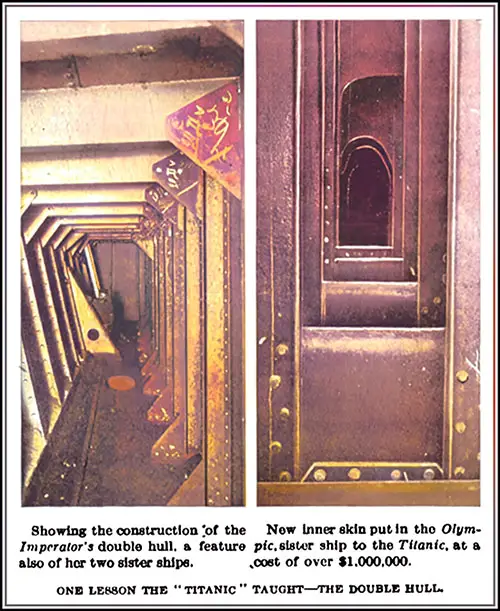
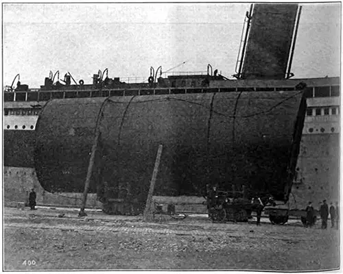
One Lesson The Titanic Taught -- The Double Hull. On the left, showing the construction of the Imperator's double hull, a feature also of her two sister ships. On the right, new inner skin put in the Olympic, sister ship to the Titanic, at a cost of over $1,000,000. The Literary Digest (26 April 1913) p. 937. | GGA Image ID # 1088bb8198
The combination of reciprocating engines with a Parsons low-pressure turbine, which has been adopted for the propelling machinery of the Olympic and Titanic, is one of the latest examples of progress in marine engineering.
The superior economy of the system is due to the fact that increased power is obtained with the same steam consumption by expanding the steam in the low-pressure turbine beyond the limits possible with the reciprocating engine.
Messrs. Harland & Wolff were among the first to see the advantages of the combination arrangement and to put the system to the test of actual experience. This was done in the case of the Laurentic, already referred to, and the successful results obtained with this vessel led to the introduction of engines of the combination type in the new White Star liners and other vessels built and building at Belfast.
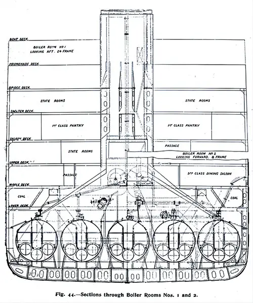
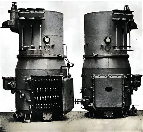
Sections Through Boiler Rooms Nos. 1 and 2. The Shipbuilder (Midsummer 1911) p. 45. | GGA Image ID # 10bcc0b520
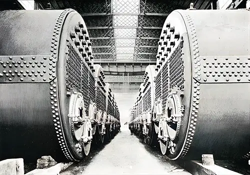
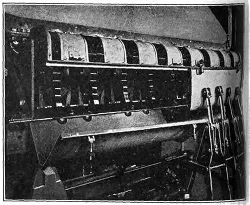
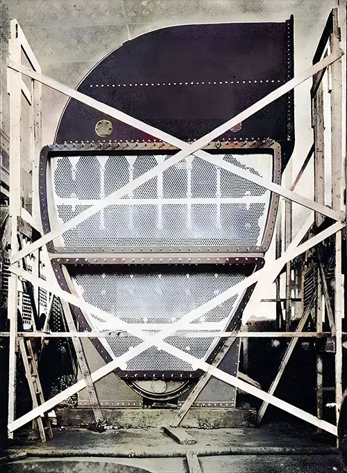
Boilers Arranged in Messrs. Harland & Wolff's Works. To be Installed on the Olympic and Titanic. The Shipbuilder (Midsummer 1911) p. 46. | GGA Image ID # 10bce2b411
Set of Boiler Uptakes. The Shipbuilder (Midsummer 1911) p. 47. | GGA Image ID # 10bd3742b9
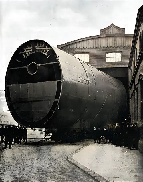
Last Funnel of the Olympic Leaving the Shops. The Shipbuilder (Midsummer 1911) p. 48. | GGA Image ID # 10bd401bf0
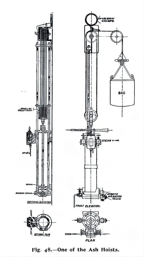
One of the Ash Hoists. The Shipbuilder (Midsummer 1911) p. 49. | GGA Image ID # 10bd8785ba
Two of the Stokehold Fans. The Shipbuilder (Midsummer 1911) p. 49. | GGA Image ID # 10bda7434f
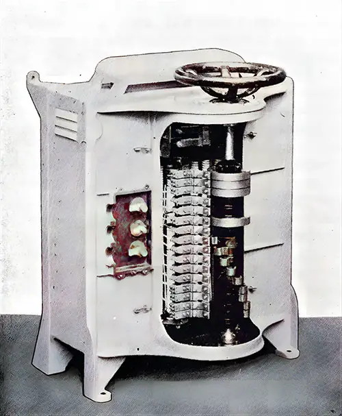
Stokehold Fan Controller with Cover Removed. The Shipbuilder (Midsummer 1911) p. 50. | GGA Image ID # 10bdbee363
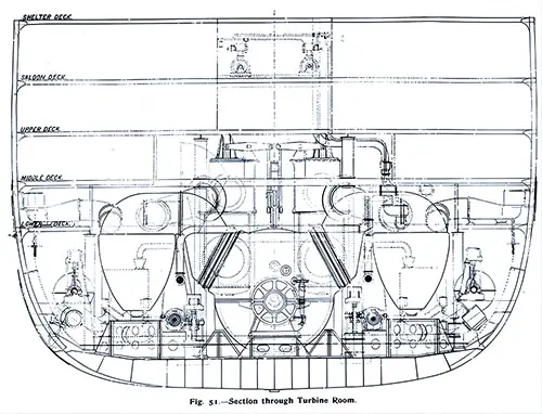
Section Through Turbine Room. The Shipbuilder (Midsummer 1911) p. 51. | GGA Image ID # 10bdc7b056
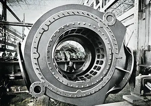
Casing of one of the Change-Over Machines. The Shipbuilder (Midsummer 1911) p. 52. | GGA Image ID # 10bdf2d0cb
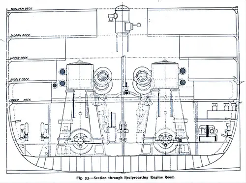
Section Through Reciprocating Engine Rome. The Shipbuilder (Midsummer 1911) p. 53. | GGA Image ID # 10be3c67d3
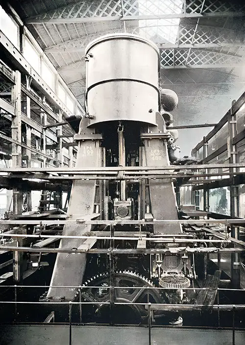
One Set of Reciprocating Engines in the Erecting Shop. The Shipbuilder (Midsummer 1911) p. 54. | GGA Image ID # 10be40741e

Port Intermediate Cylinder. The Shipbuilder (Midsummer 1911) p. 55. | GGA Image ID # 1f8e569fa1
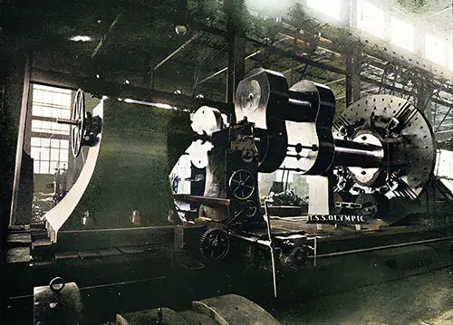
Turbine Rotor in the Lathe. The Shipbuilder (Midsummer 1911) p. 56. | GGA Image ID # 10beb8ea2f
Turbine Rotor in Process of Blading. The Shipbuilder (Midsummer 1911) p. 57. | GGA Image ID # 10becefd14
Turbine Casing. The Shipbuilder (Midsummer 1911) p. 58. | GGA Image ID # 10bf4daf90
Crank Shaft in the Lathe - For the Olympic. The Shipbuilder (Midsummer 1911) p. 59. | GGA Image ID # 10bfcbbe35
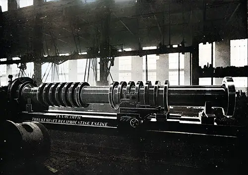
One of the Thrust Shafts for the Olympic. The Shipbuilder (Midsummer 1911) p. 59. | GGA Image ID # 10c03d3d80
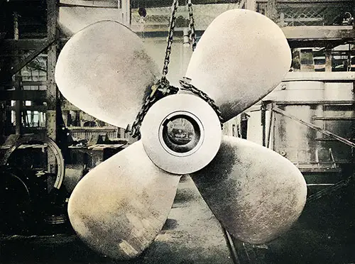
The Center Propeller. The Shipbuilder (Midsummer 1911) p. 60. | GGA Image ID # 10c0e13bee
One of the Main Condensers with Casing Partly Removed. The Shipbuilder (Midsummer 1911) p. 61. | GGA Image ID # 10c1221fa5
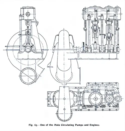
One of the Main Circulating Pumps and Engines. The Shipbuilder (Midsummer 1911) p. 62. | GGA Image ID # 10c1386887
One Set of Dual Twin Air Pumps. The Shipbuilder (Midsummer 1911) p. 63. | GGA Image ID # 10c1448873
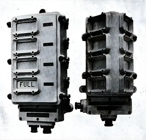
Fig. 65: Main Feed Filters of the Titanic. The Shipbuilder (Midsummer 1911) p. 64. | GGA Image ID # 10c167ff32
Direct-Contact Heater. The Shipbuilder (Midsummer 1911) p. 65. | GGA Image ID # 10c1ad77a0
One Pair of Vertical Direct-Acting Feed Pumps. The Shipbuilder (Midsummer 1911) p. 65. | GGA Image ID # 10c1b523ff
Two of the Evaporators. The Shipbuilder (Midsummer 1911) p. 65. | GGA Image ID # 10c2005cbe
Boiler Room Telegraph. Transmitter on the left, Receiver on the Right. The Shipbuilder (Midsummer 1911) p. 66. | GGA Image ID # 10c2647026
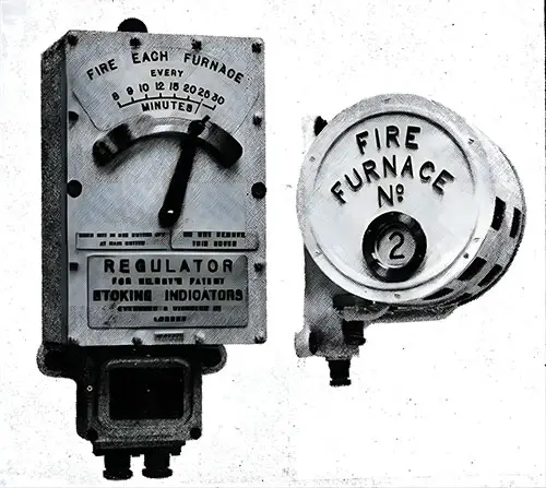
Kilroy's Stoking Indicator. Regulator on the left, Indicator on the right. The Shipbuilder (Midsummer 1911) p. 66. | GGA Image ID # 10c2e86ff9

One Set of Whistles - Used on the Olympic and Titanic. The Shipbuilder (Midsummer 1911) p. 66. | GGA Image ID # 10c2f11540
The refrigerating installation on board the Olympic and Titanic embodies all the latest facilities for efficient cold storage, ship’s provision rooms, situated aft on the lower and orlop decks (see Plate V: The White Star Triple-Screw Steamers "Olympic" and "Titanic." Deck Plans of Lower and Orlop), are most extensive, and include separate cold chambers for beef, mutton, poultry and game, fish, vegetables, fruit, milk and butter, bacon and cheese, flowers, mineral waters, wine and spirits, and champagne, which can thus be kept at the temperatures most suitable for preservation in each case.
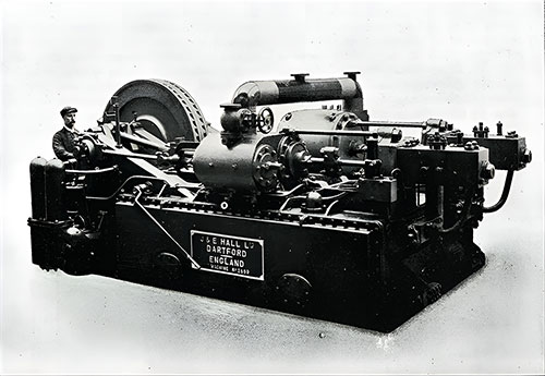
One of the Refrigerating Engines. The Shipbuilder (Midsummer 1911) p. 67. | GGA Image ID # 10c3b2d4fb
Ventilating and Heating Fans on Boat Deck. The Shipbuilder (Midsummer 1911) p. 105. | GGA Image ID # 10d0bb6add
ELECTRICITY, it need hardly be pointed out, is extensively employed in all the departments of the Olympic and Titanic. In addition to the large supply required for lighting purposes, electrical power is used for the deck cranes; cargo, boat, and engine room winches; passenger elevators; stores, mail, and pantry lifts; ventilating and stokehold fans; cabin fans; motors for the cylinder-lifting gear, turbine-turning and lifting gear, and condenser sluice valves; the workshop machine tools; conveyor for marconigrams; gymnastic apparatus; kitchen and pantry machinery, such as the ice-rocker, dough-mixers, potato-peelers, roasters, knife-cleaners, mincers, hot plates, and electric irons; electric heaters; electric baths; main steam whistles; sounding machines; stoking indicators; boiler room telegraphs; clocks; watertight doors; helm indicator; illuminated pictures; chimes; bells; loud-speaking and service telephones; submarine signaling; and wireless telegraphy.
The electrical installation, therefore, may virtually be termed the nerve system of the ship. Indeed the application of electricity is so general that much of the electrical equipment is necessarily described in the other sections of this book.
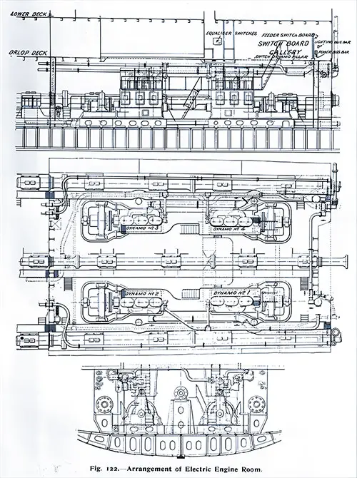
Arrangement of Electric Engine Room (Schematic). The Shipbuilder (Midsummer 1911) p. 109. | GGA Image ID # 10dcf7f38c
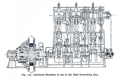
Sectional Elevation of one of the Main Generating Sets. The Shipbuilder (Midsummer 1911) p. 110. | GGA Image ID # 10dd05dd62
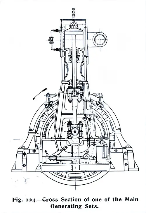
Cross Section of one of the Main Generating Sets. The Shipbuilder (Midsummer 1911) p. 110. | GGA Image ID # 10dd4a84f1
Switch Gear of Dynamos 3 and 4. The Shipbuilder (Midsummer 1911) p. 111. | GGA Image ID # 10dd59f991
Main Feeder Switchboard. The Shipbuilder (Midsummer 1911) p. 112. | GGA Image ID # 10dd72f3e9
Electrical Distribution Box. The Shipbuilder (Midsummer 1911) p. 113. | GGA Image ID # 10de24d17c

Electric Heater. The Shipbuilder (Midsummer 1911) p. 113. | GGA Image ID # 10de3c34fc
2 1/2 Ton Electric Crane. The Shipbuilder (Midsummer 1911) p. 114. | GGA Image ID # 10deac106e
3-Ton Electric Cargo Winch. The Shipbuilder (Midsummer 1911) p. 115. | GGA Image ID # 10deadcf14
10 cwt. Stores Lift. The Shipbuilder (Midsummer 1911) p. 115. | GGA Image ID # 10dec394b1
One of the Electric Baths, Open. The Shipbuilder (Midsummer 1911) p. 116. | GGA Image ID # 10ded6eefe
One of the Electric Baths, In Use. The Shipbuilder (Midsummer 1911) p. 116. | GGA Image ID # 10dee5d50d
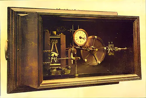
One of the Master Clocks. The Shipbuilder (Midsummer 1911) p. 117. | GGA Image ID # 10df0ecd83
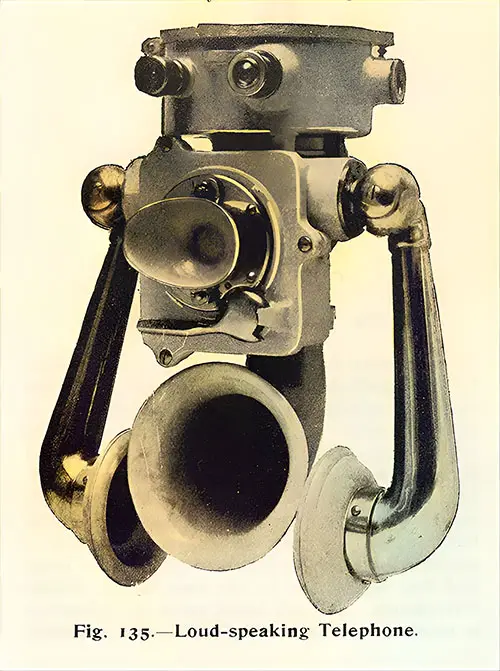
Loud-Speaking Telephone. The Shipbuilder (Midsummer 1911) p. 117. | GGA Image ID # 10df4cc8bd
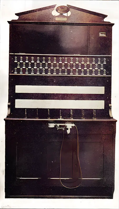
Telephone Exchange Switchboard. The Shipbuilder (Midsummer 1911) p. 118. | GGA Image ID # 10df529f1e
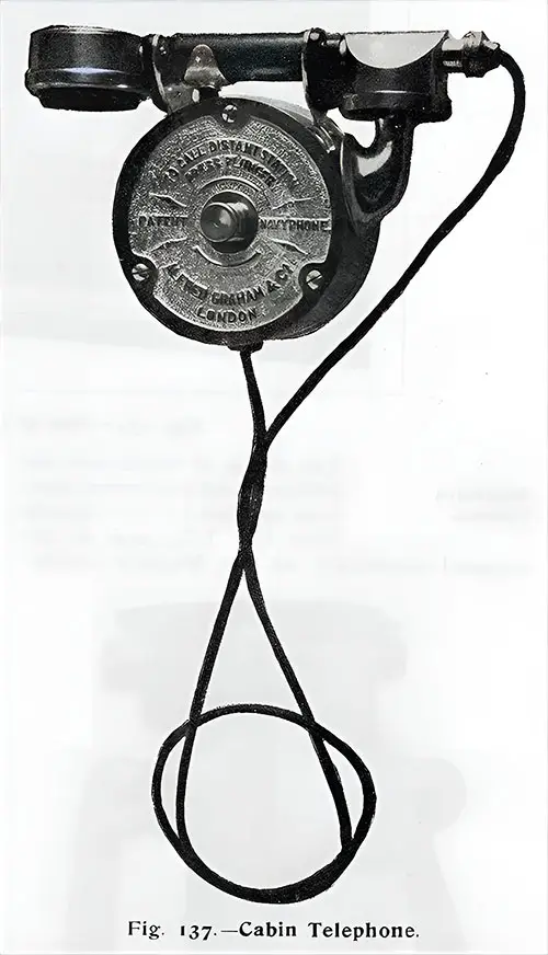
Cabin Telephone. The Shipbuilder (Midsummer 1911) p. 118. | GGA Image ID # 10df8c15e7
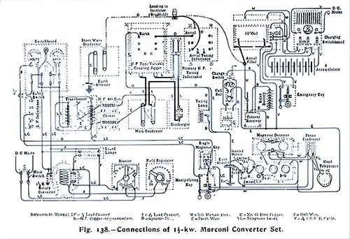
Connections of 1 1/2 KW Marconi Converter Set. The Shipbuilder (Midsummer 1911) p. 119. | GGA Image ID # 10df93a930
The working arrangements on board the Olympic and Titanic are necessarily on a scale in keeping with the great size of the vessels. The number of crew employed on board each ship for all purposes is about 860. Of these about 65 belong to the navigating department, 320 are employed in the engineers’ department, and 475 are engaged in the stewards’ and catering department.
The forward portion of the boat deck and the exposed decks at the ends of the vessel are entirely devoted to working and navigating appliances, while the management of the ship is also greatly facilitated by the working passage on the port side of E deck, which extends nearly the full length of this deck and is connected by stairways with all the principal departments.
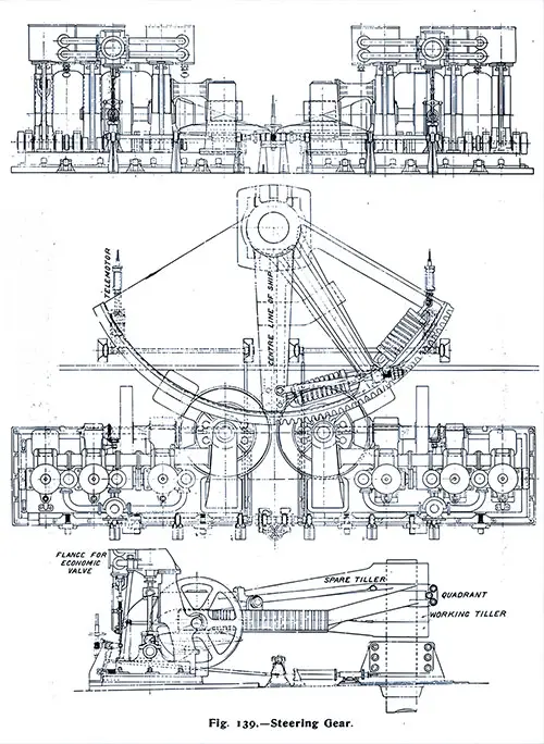
Steering Gear. The Shipbuilder (Midsummer 1911) p. 122. | GGA Image ID # 10e2d7fd20
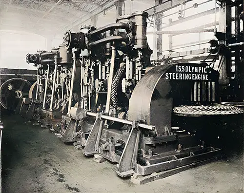
Steam Steering Engines with Spur and Bevel Gearing. The Shipbuilder (Midsummer 1911) p. 123. | GGA Image ID # 10e30618ff
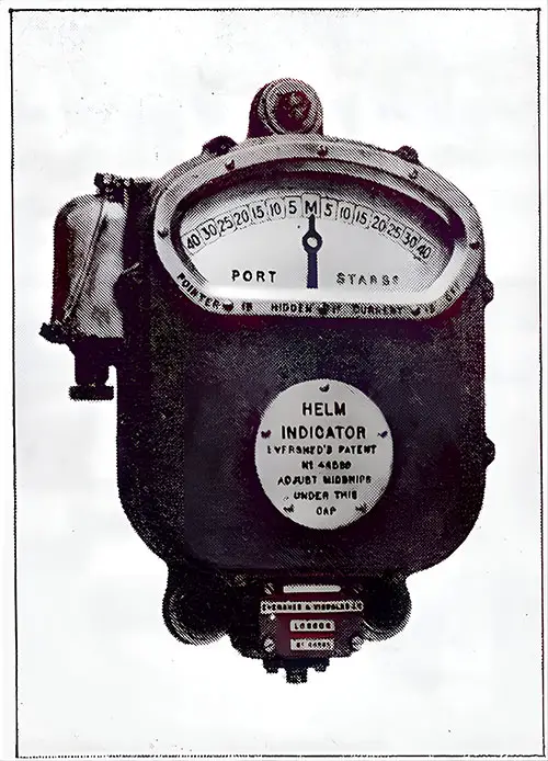
Electric Helm Indicator. The Shipbuilder (Midsummer 1911) p. 124. | GGA Image ID # 10e331edea
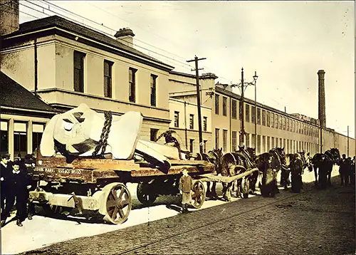
15 1/2 Ton Center Anchor Pulled by Horse-Drawn Flatbed Trailer. The Shipbuilder (Midsummer 1911) p. 124. | GGA Image ID # 10e34dffbd
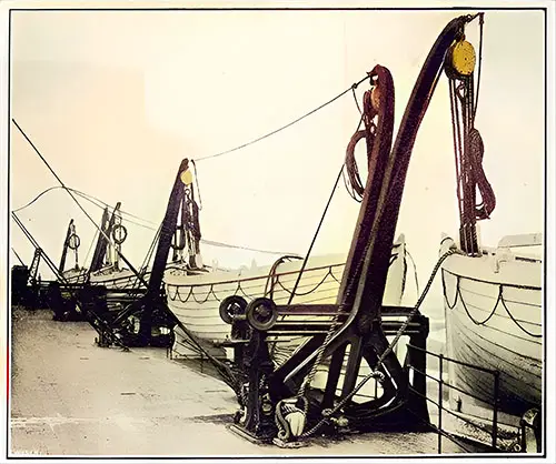
Welin Double-Acting Boat Davits. The Shipbuilder (Midsummer 1911) p. 125. | GGA Image ID # 10e35823a4
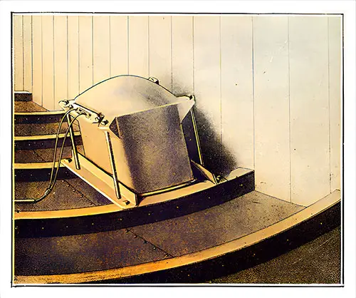
Receiving Tank for Submarine Signals. The Shipbuilder (Midsummer 1911) p. 126. | GGA Image ID # 10e37573da
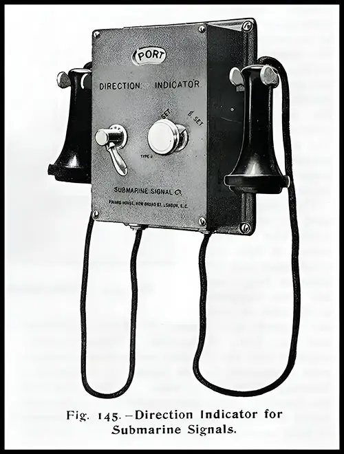
Direction Indicator for Submarine Signals. The Shipbuilder (Midsummer 1911) p. 126. | GGA Image ID # 10e37637bc
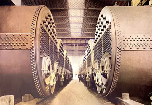
Boilers on the RMS Titanic. The Truth About the Titanic (1913) p. 52. | GGA Image ID # 1055386319
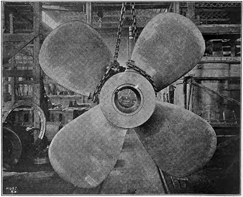
22-Ton Turbine Propellor on the RMS Titanic. The Universal Engineer (December 1911) p. 412. | GGA Image ID # 104ff0403b
Funnels of the RMS Titanic, One Installed, One on a Rail Car. The Universal Engineer (December 1911) p. 418. | GGA Image ID # 10502e45f1
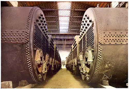
View of the Boilers for the RMS Titanic. The Unsinkable Titanic (1912) p,. 110. | GGA Image ID # 107a1cc2bf
Noteworthy Content and Engaging Details 📸
1️⃣ Refrigerating Machines and Cold Storage Systems
The Titanic’s refrigerating machines, built by J & E Hall Ltd. in Dartford, England, were essential for keeping food fresh during the long transatlantic voyages. The image of one of these systems highlights the level of sophistication involved in managing provisions for passengers and crew. This machinery was crucial for the Titanic's luxurious services, including the fine dining that became a signature of the ship.
📌 Noteworthy Image: One of the Refrigerating Machines on the Titanic (Ice and Cold Storage, July 1911). This image reflects the innovative refrigeration systems used to keep food fresh on the Titanic, underscoring the ship's commitment to luxury.
2️⃣ Electrically Operated Watertight Doors
The Titanic was equipped with electrically operated watertight doors designed to prevent flooding in the event of a hull breach. These doors were an important safety feature, providing an automated means of compartmentalizing the ship in emergencies. However, their failure to close properly during the sinking was one of the factors that contributed to the ship's tragic fate.
📌 Noteworthy Image: One of the Electrically Operated, Double-Cylinder, Watertight Doors (Popular Mechanics Magazine, June 1912). This image offers a detailed look at the watertight doors, a critical safety feature on the Titanic.
3️⃣ Main Generating Plant and Electrical Systems
The Titanic's generating plant was a marvel of early 20th-century engineering, featuring four 400 kW engines and dynamos capable of producing 16,000 amps of current. This massive power system not only provided electricity for the ship's lighting and machinery but also played a role in the ship’s sophisticated communications systems.
📌 Noteworthy Image: General View of Generating Plant (The Electrician, July 1911). This photo captures the impressive scale of the Titanic’s electrical system, emphasizing the advanced technology used to power the vessel.
Engine Room and Propulsion Systems
The Titanic was equipped with reciprocating engines and a low-pressure steam turbine for propulsion. The combination of these systems allowed the ship to achieve remarkable speed for its time. The engineering innovations in the Titanic’s propulsion systems were cutting-edge, though they ultimately couldn't prevent the ship's tragic demise.
📌 Noteworthy Image: View of the Starboard Reciprocating Engines on the RMS Titanic (The International Steam Engineer, November 1911). This image showcases the Titanic’s powerful engines, offering a detailed look at the mechanical heart of the ship.
4️⃣ Electrical Equipment for Daily Operations
The Titanic’s electrical systems were integral to its daily operations, powering everything from cargo winches to passenger elevators and telephone systems. The use of electricity throughout the ship reflects the growing role of electrical technology in all aspects of life in the early 1900s.
📌 Noteworthy Image: Main Voltmeter Pillar (The Electrician, July 1911). This image illustrates the advanced electrical infrastructure of the Titanic, which kept the ship functioning smoothly during its voyages.
Educational and Historical Relevance 📚🌐
📌 For students and teachers, this collection of images offers a window into the technological achievements of the Titanic. By examining the intricate systems that powered the ship, students can explore topics such as:
The role of engineering in ocean travel and how technology enabled the Titanic to push the boundaries of what was possible at the time.
Safety features like the watertight doors and how they were meant to mitigate disaster, despite their eventual failure.
The innovations in luxury travel aboard the Titanic, driven by sophisticated machinery that kept passengers comfortable and well-fed.
📌 For genealogists, these technical descriptions and visuals offer a look at the complex infrastructure that supported the Titanic’s crew and passengers, providing a fascinating context for tracing the lives of those who worked and traveled aboard the ship.
📌 For historians, this material provides important context for understanding the technological advancements of the early 20th century and their influence on the broader maritime industry. It also underscores the contradictions between luxury and safety that were apparent aboard the Titanic.
Final Thoughts – Why This Collection Matters 🌟
The machinery and engineering of the RMS Titanic played a central role in the ship's allure and its eventual tragedy. This collection offers a unique opportunity to explore the cutting-edge technologies that defined the Titanic, from refrigeration to propulsion and electrical systems. The innovations showcased here are not just a testament to the grandeur of the ship but also to the limitations of early 20th-century technology, which ultimately contributed to the Titanic's fate.
By studying these systems and images, students and historians can gain a deeper understanding of the Titanic’s place in the history of ocean travel and the engineering challenges of that era. The Titanic's technological legacy continues to influence modern shipbuilding and safety standards, making these materials essential for anyone studying the Titanic or the history of maritime engineering.
🔎 Research & Essay Writing Using GG Archives
📢 This is NOT a blog! Instead, students and researchers are encouraged to use the GG Archives materials for academic and historical research.
🔎 Looking for primary sources on Titanic’s lifeboat disaster? GG Archives provides one of the most comprehensive visual collections available today.