Titanic’s Powerhouse: Propelling Machinery, Boilers, and Engineering Marvels of a Legendary Ocean Liner
📌 Explore Titanic’s revolutionary propulsion system in this detailed study from The Shipbuilder (1911). Learn about her hybrid engines, massive boilers, steam turbines, and auxiliary power systems. A must-read for maritime historians, educators, and genealogy researchers.
The Shipbuilder – Propelling Machinery 🚢⚙️🔥
Introduction: Powering the Titanic – A Marvel of Marine Engineering
This section of The Shipbuilder (1911) provides a detailed exploration of Titanic’s advanced propulsion system, highlighting the ingenious combination of reciprocating engines and a Parsons low-pressure turbine. This hybrid setup offered greater fuel efficiency, higher power output, and improved steam economy, marking a major advancement in marine engineering.
For teachers, students, historians, maritime enthusiasts, and genealogists, this article provides rich technical insights and historical context on Titanic’s engineering design. The accompanying illustrations and photographs offer a rare look at the ship's boilers, turbines, and engine room, making this section invaluable for those studying early 20th-century shipbuilding and maritime history.
Table of Contents for This Section
1️⃣ Titanic’s Hybrid Propulsion System: Reciprocating Engines + Turbine
2️⃣ The Boiler System: Generating Titanic’s Power
3️⃣ The Funnels: Titanic’s Iconic Silhouettes
4️⃣ The Engine Room: Heart of the Ship’s Power
5️⃣ Turbines and Condensers: Maximizing Efficiency
6️⃣ Auxiliary Systems: Air Pumps, Feed Pumps, and Evaporators
7️⃣ Telegraphs and Indicators: Communicating with the Boiler Rooms
8️⃣ Titanic’s Whistles: The Largest Ever Made
The combination of reciprocating engines with a Parsons low-pressure turbine, which was adopted for the propelling machinery of the SS Olympic and SS Titanic, is one of the latest examples of progress in marine engineering.
The superior economy of the system is achieved by increasing power with the same steam consumption by expanding the steam in the low-pressure turbine beyond the limits possible with the reciprocating engine.
Messrs. Harland & Wolff were among the first to see the advantages of the combination arrangement and to put the system to the test of experience. This was done in the case of the Laurentic, already referred to.
The successful results obtained with this vessel led to the broader adoption of engines of the combination type, paving the way for the future of marine engineering.
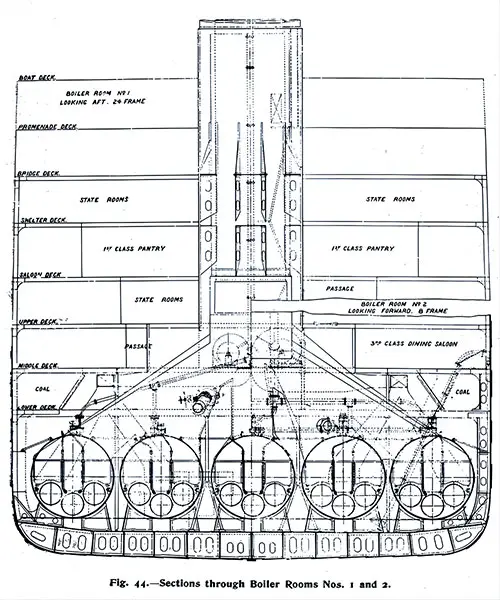
Fig. 44: Sections Through Boiler Rooms Nos. 1 and 2. The Shipbuilder, Midsummer 1911. | GGA Image ID # 10bcc0b520. Click to View a Larger Image.
Altogether, twenty-four double-ended and five single-ended boilers are in each vessel, designed for a working pressure of 215 lb. It is anticipated that these will be maintained under natural drought conditions.
The aftermost, or No. 1 boiler room contains five single-ended boilers, boiler rooms 2, 3, 4, and 5 contain five double-ended, and the foremost, or No. 6 boiler room contains four double-ended boilers.
Owing to the great width of the ships, it was found possible to arrange five boilers abreast, as shown in Fig. 44, except in the No. 6 boiler room, where, owing to increased fineness, only four abreast could be fitted.
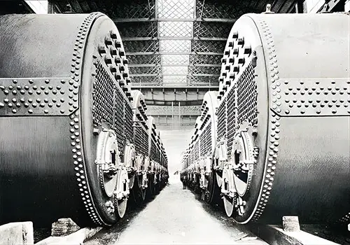
Fig. 45: Boilers Arranged in Messrs. Harland & Wolff's Works. To be Installed on the Olympic and Titanic. The Shipbuilder, Midsummer 1911. | GGA Image ID # 10bce2b411
A view of the boilers arranged in Messrs. Harland & Wolff's works is given in Fig. 45. The arrangement of uptakes, by which the smoke and waste gases are conveyed to the funnels, is necessarily very elaborate, with no less than twenty branches being required to one funnel in the case of boiler rooms 3 and 4.
The branches from adjoining boiler rooms are united immediately above the watertight bulkhead separating the rooms, the bulkhead thus forming a valuable support to the uptakes and funnel above. One set of uptakes is shown in Fig. 46, which illustrates their numerous ramifications well.
The four funnels have an elliptical cross-section and measure 24 ft 6 in by 19 ft O in. Their average height above the level of the furnace bars is 150 ft. A striking photograph of the last funnel of the SS Olympic leaving the shops is reproduced in Fig 47.
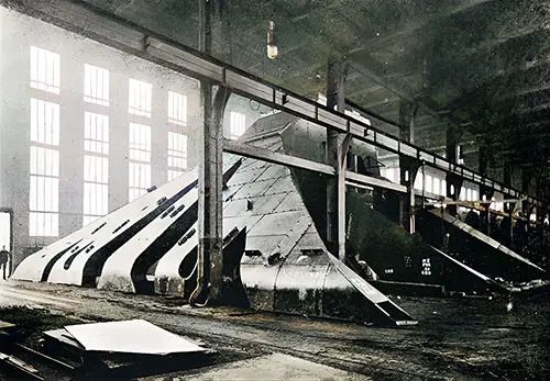
Fig. 46: Set of Boiler Uptakes. The Shipbuilder, Midsummer 1911. | GGA Image ID # 10bd3742b9
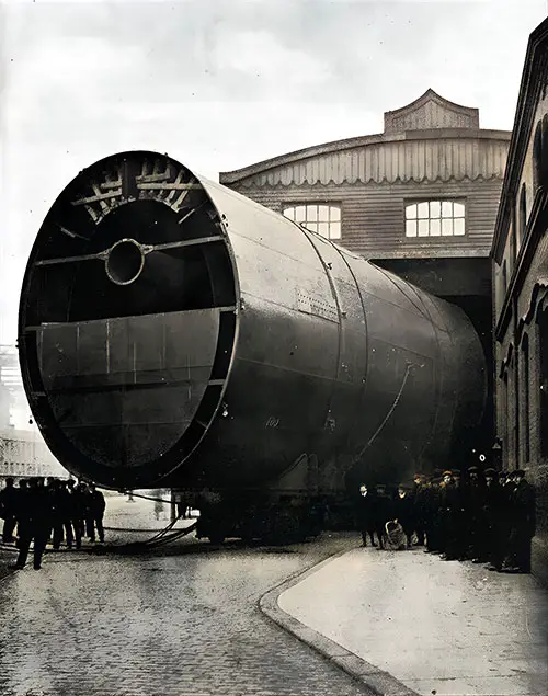
Fig. 47: Last Funnel of the Olympic Leaving the Shops. The Shipbuilder, Midsummer 1911. | GGA Image ID # 10bd401bf0
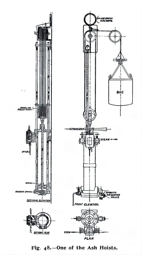
Fig. 49: One of the Ash Hoists. The Shipbuilder, Midsummer 1911. | GGA Image ID # 10bd8785ba. Click to View a Larger Image.
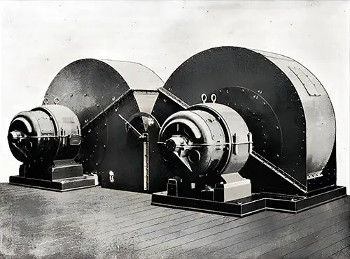
Fig. 49: Two of the Stokehold Fans. The Shipbuilder, Midsummer 1911. | GGA Image ID # 10bda7434f
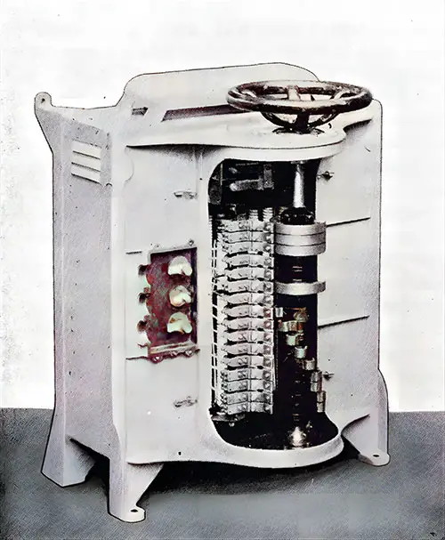
Fig. 50: Stokehold Fan Controller with Cover Removed. The Shipbuilder, Midsummer 1911. | GGA Image ID # 10bdbee363
One of the stokehold fan controllers with the cover removed is shown in Fig. 50. It will be seen that the cables are fitted permanently into screw plugs, the holes for which are bored and tapped in the joint of the cover so that they can be placed in position. The cover screwed down, making a simple and yet watertight joint. The controllers can also be worked from the stokeholds by rods supported on ball thrusts. The ball thrusts so significantly eliminate the friction that the different positions on the controller can be easily felt below.
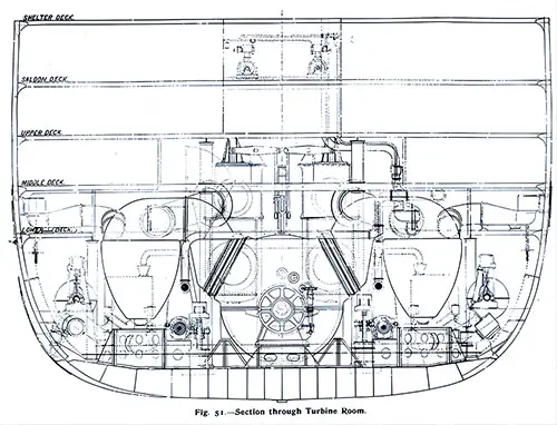
Fig. 51: Section Through Turbine Room. The Shipbuilder, Midsummer 1911. | GGA Image ID # 10bdc7b056. Click to View a Larger Image.
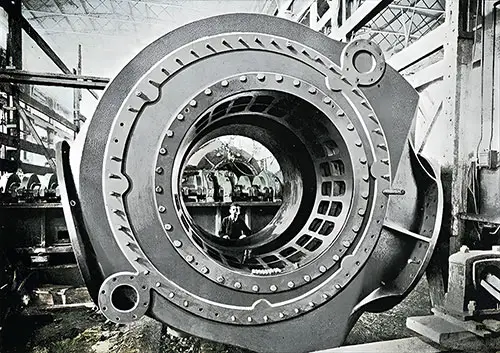
Fig. 52: Casing of one of the Change-Over Machines. The Shipbuilder, Midsummer 1911. | GGA Image ID # 10bdf2d0cb
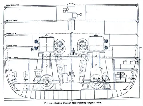
Fig. 53: Section Through Reciprocating Engine Rome. The Shipbuilder, Midsummer 1911. | GGA Image ID # 10be3c67d3. Click to View a Larger Image.
In general, the design of the engines follows the long-tried practice of Messrs. Harland & Wolff. A section through the reciprocating engine room is given in Fig. 53, a view of the starboard engines erected in the shops in Fig. 54.
Of the port intermediate cylinder in Fig. 55. From the elevation, Plate VII., it will be seen that the columns are of the "split" type, each column near its center being divided into two sections which are well spread out to form a strong base.
The engine bedplate weighs 195 tons, the columns 21 tons each, and the heaviest cylinder with liner 50 tons. The two low-pressure cylinders are placed one at each end of each set of engines, as is usual with the balancing system adopted, the order of the cylinders, beginning forward, being low-pressure, high-pressure, intermediate-pressure, and low-pressure; see Plates VII. and VIII.
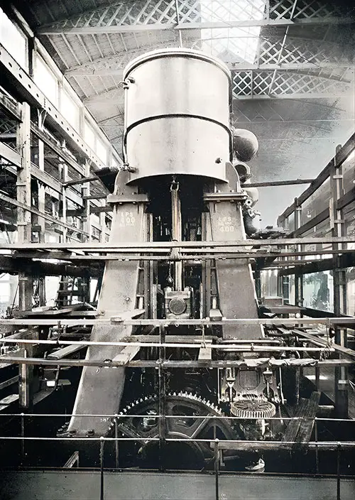
Fig. 54: One Set of Reciprocating Engines in the Erecting Shop. The Shipbuilder, Midsummer 1911. | GGA Image ID # 10be40741e
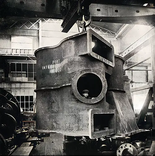
Fig. 55: Port Intermediate Cylinder. The Shipbuilder, Midsummer 1911. | GGA Image ID # 20c8251631
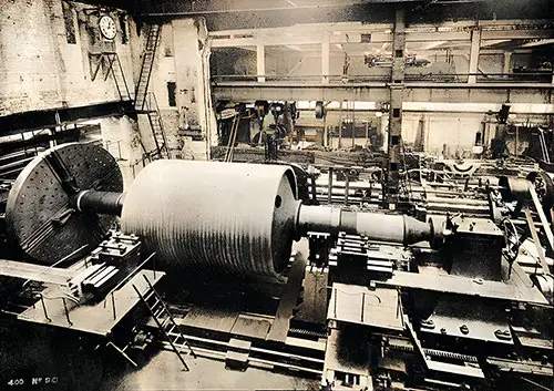
Fig. 56: Turbine Rotor in the Lathe. The Shipbuilder, Midsummer 1911. | GGA Image ID # 10beb8ea2f
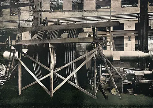
Fig. 57: Turbine Rotor in Process of Blading. The Shipbuilder, Midsummer 1911. | GGA Image ID # 10becefd14
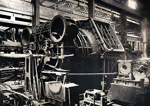
Fig. 58: Turbine Casing. The Shipbuilder, Midsummer 1911. | GGA Image ID # 10bf4daf90
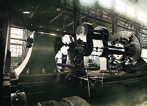
Fig. 59: Crank Shaft in the Lathe - For the Olympic. The Shipbuilder, Midsummer 1911. | GGA Image ID # 10bfcbbe35
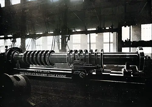
Fig. 60: One of the Thrust Shafts for the Olympic. The Shipbuilder, Midsummer 1911. | GGA Image ID # 10c03d3d80
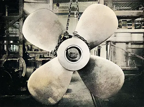
Fig. 61: The Center Propeller. The Shipbuilder, Midsummer 1911. | GGA Image ID # 10c0e13bee
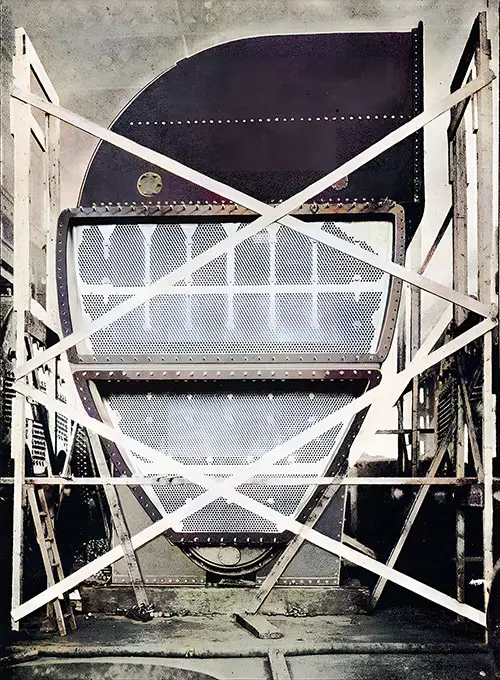
Fig. 62: One of the Main Condensers with Casing Partly Removed. The Shipbuilder, Midsummer 1911. | GGA Image ID # 10c1221fa5
There are two main condensers placed in the turbine engine room. They follow Messrs. Harland & Wolff’s standard practice. They are pear-shaped in outline, as seen in Fig. 51. The view of one of the condensers with the casing removed is reproduced in Fig. 62. The object of the pear shape is to concentrate the tube surface where the largest volume of steam is admitted.
The inlet extends the entire length of the condenser, as is usual in turbine installations, and is well-stayed vertically with division plates, which are in line with corresponding division plates in the condenser body so that an equal distribution of steam over the whole of the tube area may be secured.
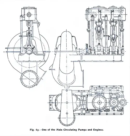
Fig. 63: One of the Main Circulating Pumps and Engines. The Shipbuilder, Midsummer 1911. | GGA Image ID # 10c1386887. Click to View a Larger Image.
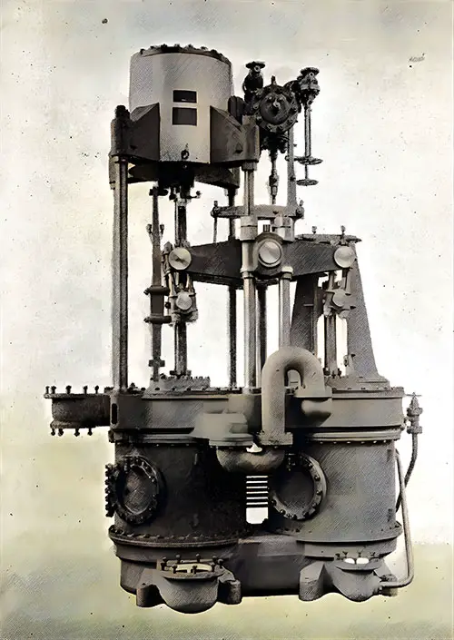
Fig. 64: One Set of Dual Twin Air Pumps. Four Pumps of the “Dual” Type, Illustrated in Fig. 64, Are Suitable for About 11,000 Indicated Horsepower (IHP) and Have Both Air and Water Barrels, 36 Inches in Diameter by 21 Inches in Stroke. The Shipbuilder, Midsummer 1911. | GGA Image ID # 10c1448873
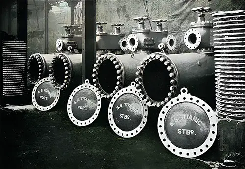
Fig. 65: Main Feed Filters of the Titanic. The Shipbuilder, Midsummer 1911. | GGA Image ID # 10c167ff32
The Return Feed System
From each condenser, the water passes into a feed tank placed on each side of the ship just above the bulkhead, dividing the engine rooms. The water drains into a control tank on each side adjacent to the Hotwell pumps in the reciprocating engine room.
From the control tanks, the water is drawn by four Weir single-cylinder direct-acting Hotwell pumps (two on each side of the ship) 14 inch diameter by 24 inch stroke, the diameter of the steam cylinder being 14 inch, and is discharged through the primary feed filters to the Weir surface feed-heater.
The main feed filters are placed against the forward engine room bulkhead (see Plate VIII) and are four in number, two on each side of the ship. They have been supplied by Messrs. Railton, Campbell, and Crawford, and the Titanic set is illustrated in Fig. 65. The total filtering area is 1,008 square feet.
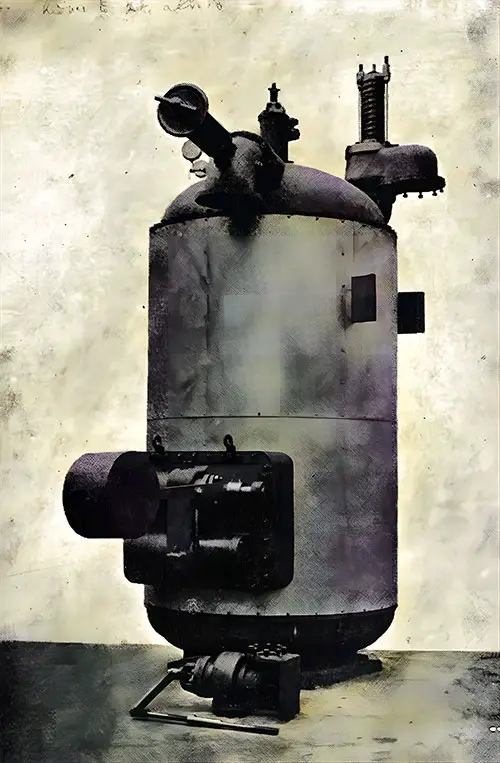
Fig. 66: Direct-Contact Heater. The Shipbuilder, Midsummer 1911. | GGA Image ID # 10c1ad77a0
The water passes from the surface feed heater to the direct-contact heater, which is placed high on the engine room forward bulkhead; see Plate VII. The direct-contact heater is suitable for dealing with 700,000 pounds of feed water per hour, and when using exhaust steam from the auxiliaries, is capable of raising the feed water temperature from 140° F. to 212 or 230° F. An illustration of this heater is given in Fig. 66. The shell is of mild steel. The direct-contact heater is so arranged that it will automatically regulate the feed and Hotwell pumps, thus ensuring these auxiliaries work in unison.
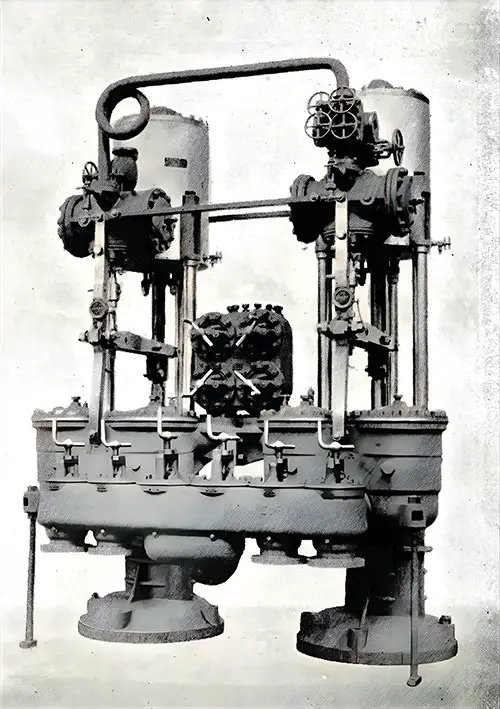
Fig. 67: One Pair of Vertical Direct-Acting Feed Pumps. The Shipbuilder, Midsummer 1911. | GGA Image ID # 10c1b523ff
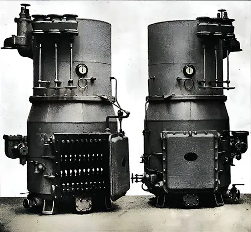
Fig. 68: Two of the Evaporators. Three Evaporators Are Placed on the Starboard Side at the End of the Turbine Room. Each Evaporator Can Produce 60 Tons of Distilled Water Per 24 Hours, Which Can Be Maintained Even After Being in Use for Several Days. The Shipbuilder, Midsummer 1911. | GGA Image ID # 10c2005cbe
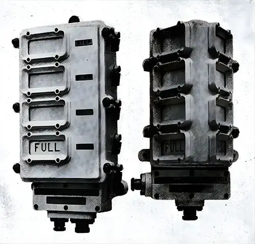
Fig. 69: Boiler Room Telegraph. Transmitter on the left, Receiver on the Right. Large Vessels Usually Have Engine Telegraphs That Transmit Orders From the Captain’s Bridge to the Starting Platform. The Shipbuilder, Midsummer 1911. | GGA Image ID # 10c2647026
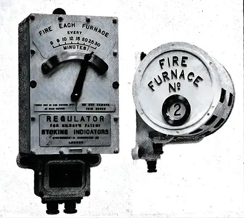
Fig. 70: Kilroy's Stoking Indicator. Regulator on the left, Indicator on the right. The Shipbuilder, Midsummer 1911. | GGA Image ID # 10c2e86ff9
The regulator is set to the rate of firing desired by the engineer, and the indicators, which are electrically operated by current switched on from the ship's circuit, give visible and audible intimation to the fireman at the exact moment when each furnace is to be fired.
Five indicators are provided in each stokehold, one for each boiler. They are regulated so that the minimum number of furnace doors will be open simultaneously and no opposite doors in a double-ended boiler open together.
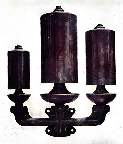
Fig. 71: One Set of Whistles - Used on the Olympic and Titanic. The Shipbuilder, Midsummer 1911. | GGA Image ID # 10c2f11540
The whistles, the largest ever made, are a sight to behold. Each set consists of three bell domes grouped with a suitable branch plate, as shown in Fig. 71. The three domes are 9 inches, 15 inches, and 12 inches in diameter, creating a striking visual. The total height from the base of the branch piece to the top of the center dome is 4 feet 2½ inches, and the extreme width over the outer dome is 3 feet 6 inches.
Key Highlights and Most Engaging Content
1️⃣ Titanic’s Hybrid Propulsion System: Reciprocating Engines + Turbine 🏗️
🔹 Titanic’s propulsion system combined reciprocating engines with a Parsons low-pressure turbine, a groundbreaking innovation for ocean liners.
🔹 This revolutionary design increased efficiency by expanding steam beyond the limits of a reciprocating engine alone.
🔹 The system was first tested on the Laurentic, and its success led to its implementation on Titanic and Olympic.
🔹 Noteworthy Image: Fig. 53: Section Through Reciprocating Engine Room 🏭
📌 Significance: Provides a rare look at the heart of Titanic’s engineering—the massive reciprocating engines that powered her across the Atlantic.
2️⃣ The Boiler System: Generating Titanic’s Power 🔥
🔹 Titanic’s massive power output was fueled by 24 double-ended and five single-ended boilers.
🔹 The boilers operated at a pressure of 215 psi, using natural draft ventilation.
🔹 The boiler rooms were arranged with five boilers abreast, allowing for maximum efficiency.
🔹 Noteworthy Image: Fig. 45: Boilers Arranged in Messrs. Harland & Wolff’s Works
📌 Significance: Offers a fascinating glimpse into the sheer scale of Titanic’s boiler system, illustrating the industrial might behind her power source.
3️⃣ The Funnels: Titanic’s Iconic Silhouettes 🚢
🔹 Titanic’s four massive funnels were elliptical, measuring 24 feet 6 inches by 19 feet.
🔹 The fourth funnel was non-functional, used for ventilation and aesthetic balance.
🔹 Each funnel stood 150 feet above the furnace grates, ensuring efficient smoke dispersion.
🔹 Noteworthy Image: Fig. 47: Last Funnel of the Olympic Leaving the Shops 🏗️
📌 Significance: Shows the incredible size of Titanic’s funnels, which became one of the most recognizable features of her design.
4️⃣ The Engine Room: Heart of the Ship’s Power ⚙️
🔹 Titanic’s reciprocating engines had four cylinders arranged in a low-pressure, high-pressure, and intermediate-pressure layout.
🔹 The engine bedplate alone weighed 195 tons, while the heaviest cylinder with liner weighed 50 tons.
🔹 The two low-pressure cylinders balanced the system, ensuring a smoother and more efficient power output.
🔹 Noteworthy Image: Fig. 54: One Set of Reciprocating Engines in the Erecting Shop ⚡
📌 Significance: Shows the massive scale of Titanic’s engines, emphasizing the engineering complexity of her propulsion system.
5️⃣ Turbines and Condensers: Maximizing Efficiency 🔄
🔹 Titanic’s low-pressure turbine converted exhaust steam into additional power, maximizing efficiency.
🔹 The turbine rotor was carefully constructed and finely bladed to extract the most energy possible.
🔹 Titanic’s pear-shaped condensers, designed for optimal steam distribution, allowed for efficient cooling and reuse of water.
🔹 Noteworthy Image: Fig. 57: Turbine Rotor in Process of Blading 🌀
📌 Significance: Highlights the precision required to manufacture Titanic’s turbines, a critical factor in her fuel efficiency.
6️⃣ Auxiliary Systems: Air Pumps, Feed Pumps, and Evaporators 🏭
🔹 Titanic’s air pumps ensured a steady steam flow, preventing pressure fluctuations.
🔹 Her feed-water filters removed impurities, protecting the boilers from contamination.
🔹 Three evaporators on the starboard side generated 60 tons of distilled water per day.
🔹 Noteworthy Image: Fig. 68: Two of the Evaporators 💧
📌 Significance: Demonstrates Titanic’s self-sufficiency, ensuring a continuous supply of clean water for her massive boilers.
7️⃣ Telegraphs and Indicators: Communicating with the Boiler Rooms ⏳
🔹 Titanic’s boiler rooms and engine rooms relied on telegraphs to relay orders.
🔹 Kilroy’s Stoking Indicator helped engineers maintain an optimal firing schedule.
🔹 The stokehold fan controllers ensured proper airflow to the boilers.
🔹 Noteworthy Image: Fig. 69: Boiler Room Telegraph 📡
📌 Significance: Shows how engineers and stokers coordinated operations below deck, ensuring smooth power delivery to the ship’s engines.
8️⃣ Titanic’s Whistles: The Largest Ever Made 📢
🔹 Titanic’s whistles were the largest ever manufactured, standing over 4 feet high.
🔹 Each whistle produced a deep, resonant sound, easily heard over vast distances.
🔹 The whistle set included three domes of varying sizes, allowing for a distinctive, recognizable tone.
🔹 Noteworthy Image: Fig. 71: One Set of Whistles - Used on the Olympic and Titanic 🎶
📌 Significance: Titanic’s whistles were not just a navigational tool, but a symbol of her grandeur and power.
Relevance for Teachers, Students, Historians, and Genealogists
👩🏫 Teachers & Students:
🔹 Perfect for science, technology, and history classes—offering an in-depth look at early 20th-century marine engineering.
🔹 A great resource for STEM projects focused on steam engines and thermodynamics.
📜 Historians & Maritime Enthusiasts:
🔹 Provides rare engineering details on Titanic’s power plant, riveting construction diagrams, and firsthand images.
🔹 Offers insight into how Titanic was a milestone in marine propulsion technology.
🧬 Genealogists & Family Historians:
🔹 Those with ancestors who worked in Titanic’s engine rooms, as engineers, or as stokers will find this section especially valuable.
🔹 Provides clues about working conditions and shipboard life for Titanic’s engineering crew.
Encouragement for Students: Essay & Research Topics
💡 Need Research Ideas?
🔹 How did Titanic’s turbine system improve efficiency over previous ocean liners?
🔹 Why were Titanic’s whistles the largest ever made?
🔹 What role did feed pumps and evaporators play in Titanic’s engineering design?
🚢 Dive into the world of Titanic’s engineering excellence, where steam and steel powered a legend. 🌊

