Titanic Deck Plans: A Blueprint of the Ill-Fated Liner’s Design, Layout, and Tragic Flaws
Superb Collection of Deck Plans are provided for Boat Deck and Promenade Deck A, Poop Deck, Bridge Deck B, Forecastle Deck, Shelter Deck C, Saloon Deck D, Upper Deck E, Middle Deck F, Lower Deck G, Orlop Deck, Lower Orlop Deck, and Tank Top. Longitudinal Section Showing Decks and Watertight Bulkheads, Transverse (Amidship) Section, Cross-Section, Public Rooms, Staterooms, Boiler Rooms Nos 1 and 2, and Engine Rooms.
🚢 RMS Titanic Deck Plans: A Blueprint of Maritime History
📖 Review & Summary: A Comprehensive Look at Titanic's Engineering & Design
The "RMS Titanic Images – Deck Plans" collection is an unmatched resource for understanding the structure, design, and layout of one of history’s most famous ocean liners. Featuring detailed deck plans, cross-sections, lifeboat arrangements, and technical drawings, this archive provides an in-depth look at how Titanic was built and how its design played a role in both its grandeur and its tragic fate.
For teachers, students, historians, genealogists, and maritime enthusiasts, these deck plans offer a wealth of information that can be used for academic research, historical analysis, and discussions on early 20th-century ocean travel. This collection reveals the engineering marvel that Titanic was—its massive scale, luxurious accommodations, and the structural weaknesses that ultimately led to its sinking.
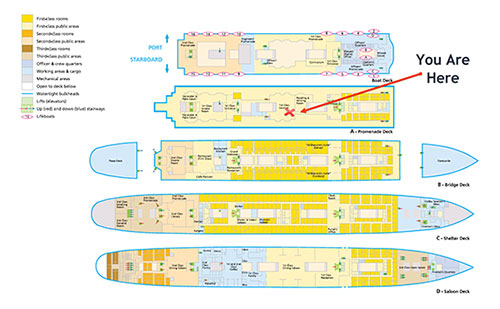
Deck Plans of Boat Deck and Decks A-D of the RMS Titanic Including Placement of Lifeboats With You Are Here Insert. (Insert Added for Illustration Purposes). | GGA Image ID # 1109100e02. Click to View Larger Image.
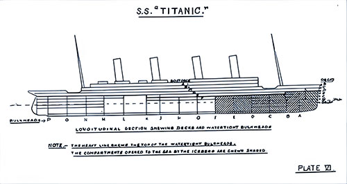
SS Titanic - Longitudinal Section Showing Decks and Watertight Bulkheads. How to Save a Big Ship from Sinking (1915) p. 121. | GGA Image ID # 10a2deecbc. Click to View Larger Image.
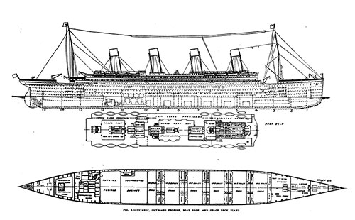
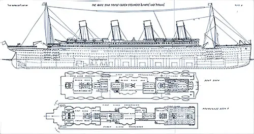
Titanic Outboard Profile, Boat Deck and Orlop Deck Plans. International Marine Engineering (May 1912) p. 199. | GGA Image ID # 1050d41670. Click to View Larger Image.
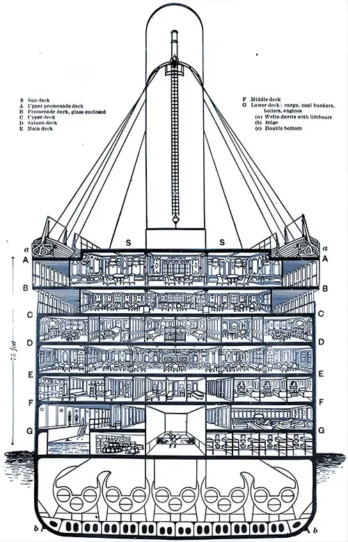
Transverse (Amidship) Section of the Titanic. Loss of the Steamship Titanic (1912) p. 89. | GGA Image ID # 100b7d712b. Click to View Larger Image.
Fig. 2— Broadside Elevation of the Vessel, Indicating Positions of Decks and Water Tight Bulkheads, Illustrating the Necessity of Carrying Bulkheads to Upper Decks, and Showing How Flooding of Compartments Forward of Boiler Rooms Would Bring the Head down so That Water Would Flow over Bulkheads into Other Compartments, Sinking Being Inevitable. The Titanic Was 882 Feet 6 Inches Long: 92 Feet 6 Inches Beam; 46,328 Tons Register and Had Accommodations for 3,500 People as Passengers and Crew. She Was the Largest and Most Luxurious Ocean Steamship Ever Built, with 11 Decks and 15 Watertight Bulkheads the Distance from the Bottom of Her Keel to the Top of the Captain's House Was 105 Feet 7 Inches. Popular Mechanics Magazine (June 1912) p. 806-b & 807-b. | GGA Image ID # 1082ea705f. Click to View Larger Image.
Longitudinal Section of Titanic Showing in Heavy Lines the Transverse Bulkheads. Suggested plan by which suflicient boats could be carried to accommodate the ship's full complement. Boats carried amidship on tracks on which they can be moved to either side of the ship. Scientific American (27 April 1912) p. 373d. | GGA Image ID # 10a3617b52. Click to View Larger Image.
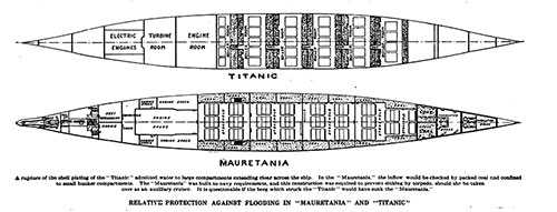
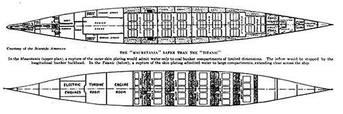
Relative Protection Against Flooding in Mauretania and Titanic. A rupture of the shell plating of the Titanic admitted water to large compartments extending clear across the ship. In the Mauretania, the inflow would be checked by packed coal and confined to small bunker compartments. The Mauretania was built to Navy requirements, and this construction was required to prevent sinking by a torpedo, should she be taken over as an auxiliary cruiser. It Is questionable if the berg which struck the Titanic would have sunk the Mauretania. Scientific American (11 May 1912) p. 417b. | GGA Image ID # 10a5ab9679. Click to View Larger Image.
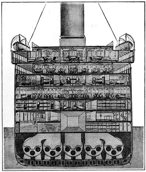
Cross-Section, Drawn to Exact Scale, Through the Titanic. Scientific American (11 May 1912) p. 418b. | GGA Image ID # 10a5c11e1a
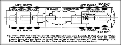
Fig. 1—Boat-Deck Plan of the "Titanic," Showing How Lifeboats Were Located, 60 Feet above the Water. There Were 16 Large Boats, to Be Swung out by the Davits before Lowering, and Two Sea Boats, Already Swung out and Ready for Instant Use in Case of Man Overboard or Other Emergency. There Was Room for More Boats on This and Other Decks of the Liner. Popular Mechanics Magazine (June 1912) p. 806-a & 807-a. | GGA Image ID # 1082947e52. Click to View Larger Image.
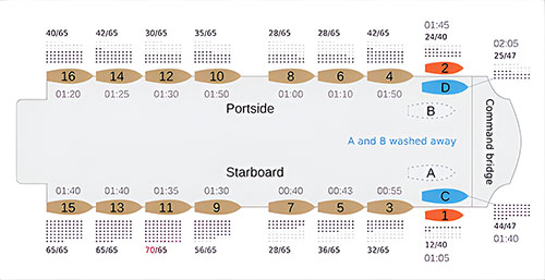
Graphic Depicting the Lifeboat Arrangement on the RMS Titanic's Boat Deck with Launch Information Including Launch Time, Number of Persons Occupying Each Lifeboat, Capacity of Each Lifeboat, and a "Metered" Snapshot of Just How Empty or Full Each Lifeboat Was on 15 April 1912. Public Domain Image. | GGA Image ID # 10ed6d0e67. Click to View Larger Image.
Boat Deck of Titanic Showing 20 Lifeboats Carrying About 1000 Passengers and Crew. Scientific American (27 April 1912) p. 373b. | GGA Image ID # 10a3017960. Click to View Larger Image.
Plan of Boat Deck Showing Suggested Accommodations for 56 Lifeboats Carrying About 3100 Passengers and Crew. Scientific American (27 April 1912) p. 373c. | GGA Image ID # 10a307d1f6. Click to View Larger Image.
Arrangement of Lifeboats on the Deck of the Titanic, as Originally Planned. On its actual maiden trip the ship carried only a single row of boats on each side, and four extra, twenty in all. Scientific American (4 May 1912) p. 404c. | GGA Image ID # 10a544fd39. Click to View Larger Image.
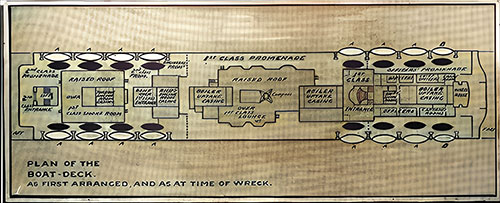
The Boats the "Titanic" Carried and Those She Might Have Carried: The Ill-Fated Liner's Boat-Deck as Planned and as It Was at the Time of the Disaster. The Illustrated London News (11 May 1912) p. 691. | GGA Image ID # 10086f3baa
How Lifeboats For All Could Be Carried. On the Left, Boat Deck of the Titanic Showing 20 Lifeboats Carrying About 1,000 Passengers. On the Right, Plan of Boat Deck Showing Suggested Accommodations for 56 Boats Carrying About 3,100 Passengers. © Scientific American. The Literary Digest (11 May 1912) p. 982. | GGA Image ID # 1086a1115f. Click to View Larger Image.
Deck Plan of Boat Deck of the RMS Titanic. The Unsinkable Titanic (1912) p,. 45. | GGA Image ID # 10752aaf8d. Click to View Larger Image.
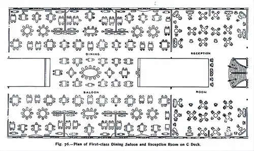
Fig. 76: Plan of First Class Dining Saloon and Reception Room on C Deck. The Shipbuilder (Midsummer 1911) p. 73. | GGA Image ID # 10c42942f5. Click to View Larger Image.
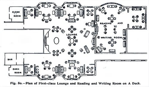
Fig. 80: Plan of First Class Lounge, Reading and Writing Room on A Deck. The Shipbuilder (Midsummer 1911) p. 77. | GGA Image ID # 10c4728a45. Click to View Larger Image.
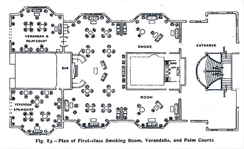
Fig. 83: Plan of First Class Smoking Room, Verandahs, and Palm Courts. The Shipbuilder (Midsummer 1911) p. 80. | GGA Image ID # 10c5c28816. Click to View Larger Image.
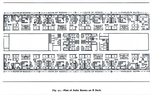
Fig. 91: Plan of Suite Rooms on B Deck. The Shipbuilder (Midsummer 1911) p. 85. | GGA Image ID # 10c8be247e. Click to View Larger Image.
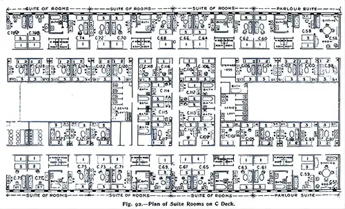
Fig. 92: Plan of Suite Rooms on C Deck. The Shipbuilder (Midsummer 1911) p. 86. | GGA Image ID # 10c8dcc9ba. Click to View Larger Image.
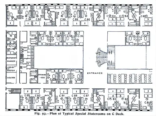
Fig. 93: Plan of Typical Special Stateroom on C Deck. The Shipbuilder (Midsummer 1911) p. 87. | GGA Image ID # 10c9151834. Click to View Larger Image.
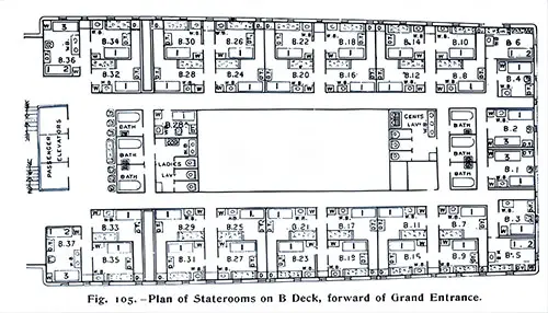
Fig. 105: Plan of Stateroom on B Deck, Forward of Grand Entrance. The Shipbuilder (Midsummer 1911) p. 94. | GGA Image ID # 10cba96bc9. Click to View Larger Image.
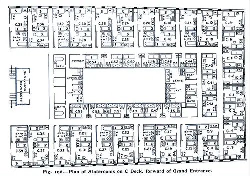
Fig. 106: Plan of Staterooms on C Deck, Forward of Grand Entrance. The Shipbuilder (Midsummer 1911) p. 94. | GGA Image ID # 10cbc541d3. Click to View Larger Image.
Plates from the Special Issue of The Shipbuilder that provide detailed deck plans, sectional views, Elevation of Boiler Rooms Nos 1 and 2, Elevation of Engine Rooms, and a Plan of the Engine Rooms. Deck Plans are provided for Boat Deck and Promenade Deck A, Poop Deck, Bridge Deck B, Forecastle Deck, Shelter Deck C, Saloon Deck D, Upper Deck E, Middle Deck F, Lower Deck G, Orlop Deck, Lower Orlop Deck, and Tank Top.
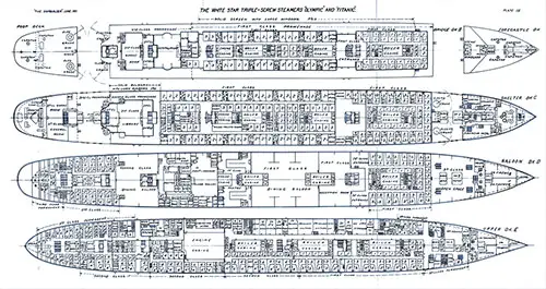
Plate 3: Plans for Boat Deck and Promenade Deck. The White Star Triple-Screw Steamers Olympic and Titanic. The Shipbuilder (Midsummer 1911) p. 120-121. | GGA Image ID # 10e159037b. Click to View Larger Image.
Plate 3(a): Boat Deck Plan. The Shipbuilder (Midsummer 1911) p. 120-121. | GGA Image ID # 10e1a447c7. Click to View Larger Image.
Plate 3(b): First Class Promenade Deck A Plan. The Shipbuilder (Midsummer 1911) p. 120-121. | GGA Image ID # 10e1866347. Click to View Larger Image.
Plate 4: Deck Plans for Poop Deck, Bridge Deck B, Forecastle Deck, Shelter Deck C, Saloon Deck D, and Upper Deck E. The White Star Triple-Screw Steamers Olympic and Titanic. The Shipbuilder (Midsummer 1911) p. 120-121. | GGA Image ID # 10e1e370ec. Click to View Larger Image.
Plate 4a: Deck Plans for Poop Deck, Bridge Deck B and Forecastle Deck. The White Star Triple-Screw Steamers Olympic and Titanic. The Shipbuilder (Midsummer 1911) p. 120-121. | GGA Image ID # 10e7ecc537. Click to View Larger Image.
Plate 4b: Deck Plans for Shelter Deck C. The White Star Triple-Screw Steamers Olympic and Titanic. The Shipbuilder (Midsummer 1911) p. 120-121. | GGA Image ID # 10e8cab74c. Click to View Larger Image.
Plate 4c: Deck Plans for Saloon Deck D. The White Star Triple-Screw Steamers Olympic and Titanic. The Shipbuilder (Midsummer 1911) p. 120-121. | GGA Image ID # 10e8d3c105. Click to View Larger Image.
Plate 4d: Deck Plans for Upper Deck E. The White Star Triple-Screw Steamers Olympic and Titanic. The Shipbuilder (Midsummer 1911) p. 120-121. | GGA Image ID # 10e941bfce. Click to View Larger Image.
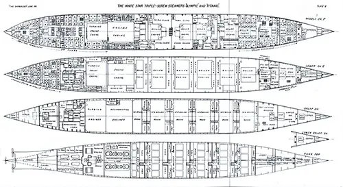
Plate 5: Deck Plans - Middle Deck F, Lower Deck G, Orlop Deck, Lower Orlop Deck, and Tank Top. The White Star Triple-Screw Steamers Olympic and Titanic. The Shipbuilder (Midsummer 1911) p. 120-121. | GGA Image ID # 10e1febffd. Click to View Larger Image.
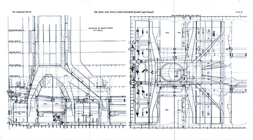
Plate 6: Elevation of Boiler Rooms Nos 1 and 2 - The White Star Triple-Screw Steamers Olympic and Titanic. The Shipbuilder (Midsummer 1911) p. 120-121. | GGA Image ID # 10e21e3261. Click to View Larger Image.
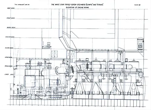
Plate 7: Elevation of Engine Rooms. The White Star Triple-Screw Steamers Olympic and Titanic. The Shipbuilder (Midsummer 1911) p. 120-121. | GGA Image ID # 10e24fff78. Click to View Larger Image.
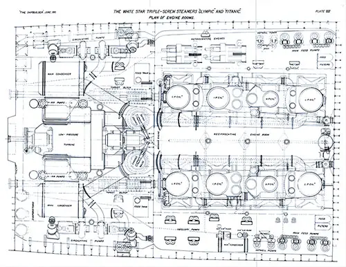
Plate 8: Plan of Engine Rooms. The White Star Triple-Screw Steamers Olympic and Titanic. The Shipbuilder (Midsummer 1911) p. 120-121. | GGA Image ID # 10e2884479. Click to View Larger Image.
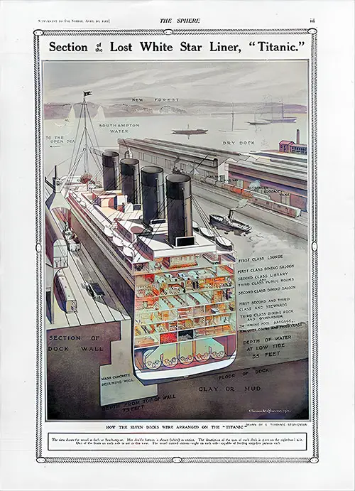
Lost White Star Liner Titanic: How the Seven Decks Were Arranged on the Titanic. The Sphere (20 April 1912) p. 3 of the Supplement. | GGA Image ID # 10f9fed51f
The Mauretania Safer Than the Titanic. In the Mauretania (upper plan), a rupture of the outer skin plating would admit water only to coal bunker compartments of limited dimensions. The longitudinal bunker bulkhead would stop the inflow. In the Titanic (below), a rupture of the skin plating admitted water to large compartments, extending clear across the ship. © Scientific American. The World To-Day (June 1912) p. 2376s. | GGA Image ID # 1097a55566. Click to View Larger Image.
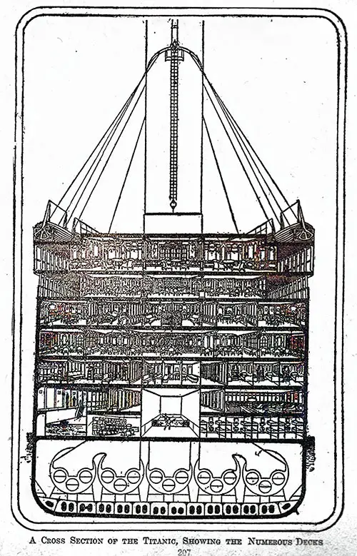
Cross Section of Titanic Showing Numerious Decks. Wreck and Sinking of the Titanic (1912) p. 206. | GGA Image ID # 1090640c5c
🏛️ Why This Collection is Essential for Titanic & Maritime Research
🌊 Genealogists: Tracing Titanic Passengers & Their Experience
For family historians and genealogists, these deck plans provide a rare opportunity to visualize where passengers lived, dined, and spent their final moments on the Titanic.
📌 Key Images for Genealogists:
✅ "Deck Plan of First-Class Staterooms on B & C Decks" – Helps locate passenger accommodations, especially for those researching ancestors who traveled in first-class.
✅ "Plan of Third-Class Sections on Lower Decks" – A valuable reference for those tracing immigrant ancestors who traveled in steerage.
✅ "Titanic Lifeboat Arrangement & Launch Information" – A critical resource for studying lifeboat assignments and survival rates by class.
💡 Why it’s relevant:
✔️ Family researchers can identify where their ancestors stayed on the ship 📜.
✔️ Immigration historians can examine third-class conditions and the ship’s role in transatlantic migration 🚢.
✔️ Descendants of Titanic passengers can connect with their relatives’ experiences through accurate deck layouts 🏛️.
🏛️ Historians & Educators: Understanding Titanic’s Engineering & Tragedy
For teachers, students, and historians, these deck plans serve as an extraordinary educational resource that helps explain how Titanic was built, its technological advancements, and the design flaws that contributed to its sinking.
📌 Key Images for Educators & Historians:
✅ "Longitudinal Section Showing Decks and Watertight Bulkheads" – Provides a clear visual of Titanic’s bulkhead system and why it failed to prevent sinking.
✅ "Boat-Deck Plan of the Titanic Showing Lifeboat Locations" – Highlights lifeboat shortages and the disaster’s impact on maritime safety regulations.
✅ "Comparison of Titanic & Mauretania's Flooding Protection" – A fascinating technical analysis of how Titanic's design was inferior in terms of water containment.
💡 Why it’s relevant:
✔️ Perfect for classroom discussions on the Titanic disaster, ship engineering, and maritime safety regulations 📚.
✔️ Provides primary-source visuals for historical accuracy in research papers and documentaries 🎥.
✔️ Explores how shipbuilding advancements evolved post-Titanic tragedy ⚓.
🌍 Maritime Enthusiasts: A Deep Dive into Titanic’s Deck-by-Deck Layout
For those who admire the golden age of ocean liners, this collection is a must-see blueprint of Titanic’s luxurious accommodations and state-of-the-art engineering.
📌 Key Images for Maritime Enthusiasts:
✅ "Fig. 76: Plan of First-Class Dining Saloon & Reception Room on C Deck" – A glimpse into Titanic’s fine dining experience.
✅ "Fig. 83: Plan of First-Class Smoking Room, Verandahs, and Palm Courts" – Highlights the lavish lifestyle of Titanic’s wealthiest passengers.
✅ "Plate 7: Elevation of Engine Rooms" – A fascinating look at Titanic’s power source and propulsion system.
💡 Why it’s relevant:
✔️ Great for ship model builders, maritime historians, and collectors 🏗️.
✔️ Explains Titanic’s technological advancements in shipbuilding 📖.
✔️ Highlights the grandeur of early 20th-century transatlantic travel 🏨.
📸 Noteworthy Images & Their Significance
📷 "Deck Plans of Boat Deck and Decks A-D Including Lifeboat Placement"
🔹 A critical map of Titanic’s upper decks, showing where lifeboats were located and how few were actually available.
📷 "Longitudinal Section Showing Titanic’s Watertight Bulkheads"
🔹 Explains why Titanic’s "unsinkable" design failed, leading to the ship's catastrophic flooding.
📷 "Cross-Section of Titanic"
🔹 Provides a clear, detailed view of Titanic’s multiple decks and passenger accommodations.
📷 "Plan of Boat Deck Showing Suggested Accommodations for 56 Lifeboats"
🔹 A what-if scenario that illustrates how Titanic could have saved every passenger if it had been outfitted properly.
📷 "Plate 8: Plan of Titanic’s Engine Rooms"
🔹 Offers a rare glimpse into the engineering powerhouse that propelled Titanic across the Atlantic.
🔎 Encouraging Research & Essay Writing Using GG Archives
📢 This is NOT a blog! Instead, students and researchers are encouraged to use the GG Archives materials for academic and historical research.
🔎 Looking for primary sources on Titanic’s design? GG Archives provides one of the most comprehensive deck plan collections available today.
🚢 Final Thoughts: The Titanic’s Design Like You’ve Never Seen Before
This incredible collection of deck plans offers an in-depth perspective on Titanic’s structure, luxury, and the fatal design flaws that led to its sinking. Whether you are researching the ship’s construction, passenger experience, or the engineering failures of the disaster, this archive provides invaluable insights into one of the most famous maritime tragedies in history.
📌 Who Should Use This Resource?
✔️ Teachers & students – A technical case study on Titanic’s construction and sinking 📚.
✔️ Genealogists – Provides visuals of where passengers and crew were located on the ship 📜.
✔️ Historians & maritime buffs – A detailed breakdown of Titanic’s decks, engineering, and safety failures ⚓.
✔️ Writers & museum professionals – Essential for accurate historical storytelling & Titanic exhibitions 🎭.
📢 💡 Explore Titanic’s deck plans like never before with GG Archives’ extensive collection! 🌊🚢

